
.png)

.png)







Home
 News Center
Wafer Defect Inspection: Solving the "Spiral Motion Trajectory" and "Equal Arc-Length Triggering" Challenges
News Center
Wafer Defect Inspection: Solving the "Spiral Motion Trajectory" and "Equal Arc-Length Triggering" Challenges
News Center
Wafer Defect Inspection: Solving the "Spiral Motion Trajectory" and "Equal Arc-Length Triggering" Challenges
Wafer Defect Inspection: Solving the "Spiral Motion Trajectory" and "Equal Arc-Length Triggering" Challenges
 2026-06-03
Share:


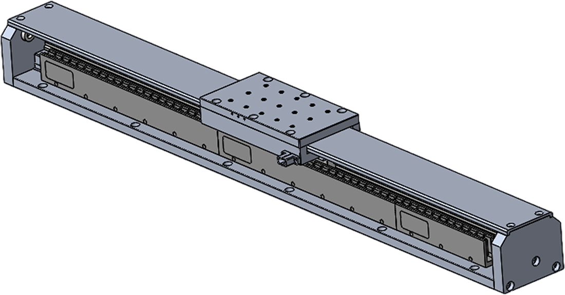
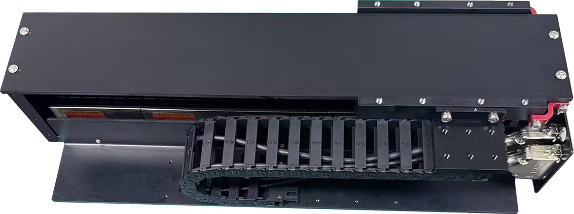
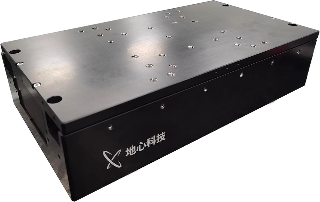
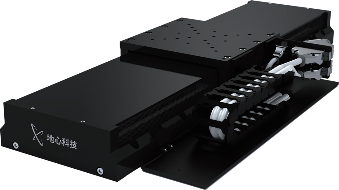
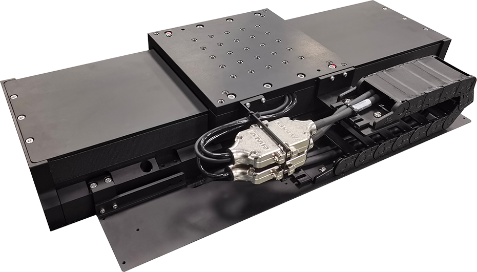
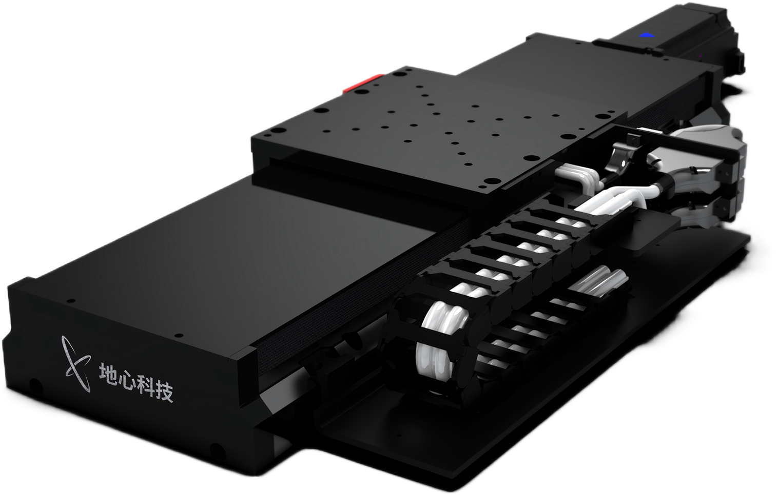
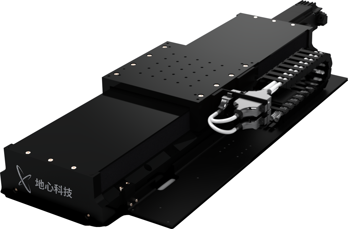
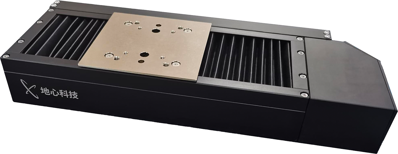
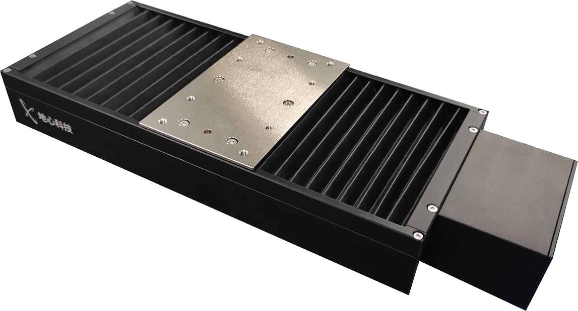
"Coretech's high-precision SMH225LM linear motion stage, paired with the RAB series high-precision air-bearing rotary stage, perfectly achieves spiral motion in wafer defect inspection applications, and enables equal arc-length triggering for high-speed camera image acquisition, playing a vital role in the field of wafer defect inspection."
01 Wafer Defect Inspection
Wafer defect optical inspection has long been an engineering challenge that evolves alongside the development of IC manufacturing. Wafer defect inspection must accurately identify defects such as voids, pits, and scratches, and obtain detailed information including defect location, area size, and more. It must also meet the speed and throughput requirements of large-scale industrial production to achieve rapid inspection.
There are two common methods for wafer defect inspection in the semiconductor industry: Automated Optical Inspection (AOI) and Scanning Electron Microscope (SEM) systems. AOI systems are based on optical principles, primarily using designed illumination systems to light the target (with bright-field, dark-field, and transmitted-field imaging modes), imaging the object with an imaging system, converting the image to digital signals via image sensors (CMOS/CCD), and performing defect detection through image analysis on a host computer with image processing software. SEM systems, on the other hand, focus a highly energetic, extremely narrow electron beam onto the sample surface, collecting various physical information by detecting particles generated from the interaction between the scanning beam and the material point by point.
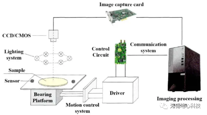
Schematic diagram of a typical AOI inspection system
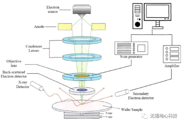
Schematic diagram of a typical SEM inspection system
02 "Spiral" Motion Trajectory
Whether in AOI or SEM inspection systems, the motion stage carrying the wafer is a critical component of the system. Current chip production processes typically require inspection equipment for 4-inch/6-inch wafers to achieve measurement speeds exceeding 100 wafers per hour. Conventional XY linear motion stages struggle to meet these speed requirements.
High-speed air-bearing rotary stages, however, can typically achieve rotational speeds of thousands of RPM or more. In this context, using a high-precision linear-motor-driven X-axis combined with a linear-motor-driven air-bearing rotary stage to inspect the wafer under high-speed rotation is a highly suitable solution. In this case, the wafer's motion trajectory follows a spiral path.
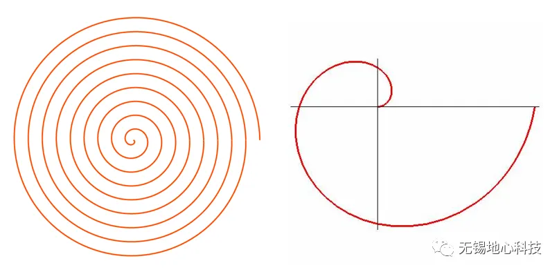
Typical spiral motion trajectory
During spiral motion of the wafer, to ensure measurement accuracy, it is essential that the sampling points of the image sensor are as uniformly spaced as possible. Since the wafer is in a rotating state, only the angular velocity of the rotary stage can be controlled. To achieve uniform sampling by the image sensor, the linear velocity of the measured object within the sensor's field of view must be uniform.
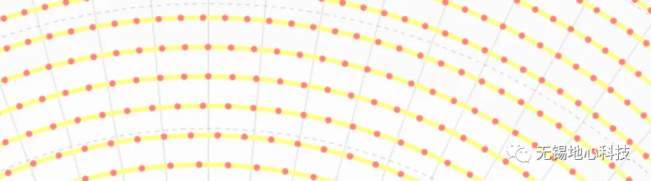
03 "Equal Arc-Length" Triggering
To ensure measurement accuracy and maintain uniform sampling spacing of the image sensor, the motion mechanism is often required to provide trigger signals that tell the image sensor when to sample. In a spiral motion trajectory, this requires the motion mechanism to trigger the image sensor at equal arc-length intervals.
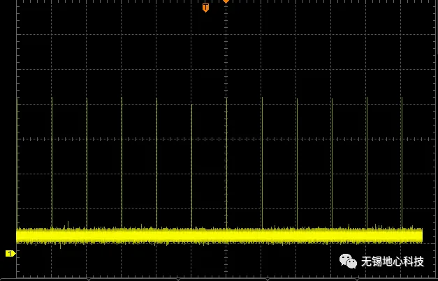
04 Coretech Solutions
As outlined above, Coretech provides its answer to the equal arc-length triggering challenge under spiral motion trajectories.
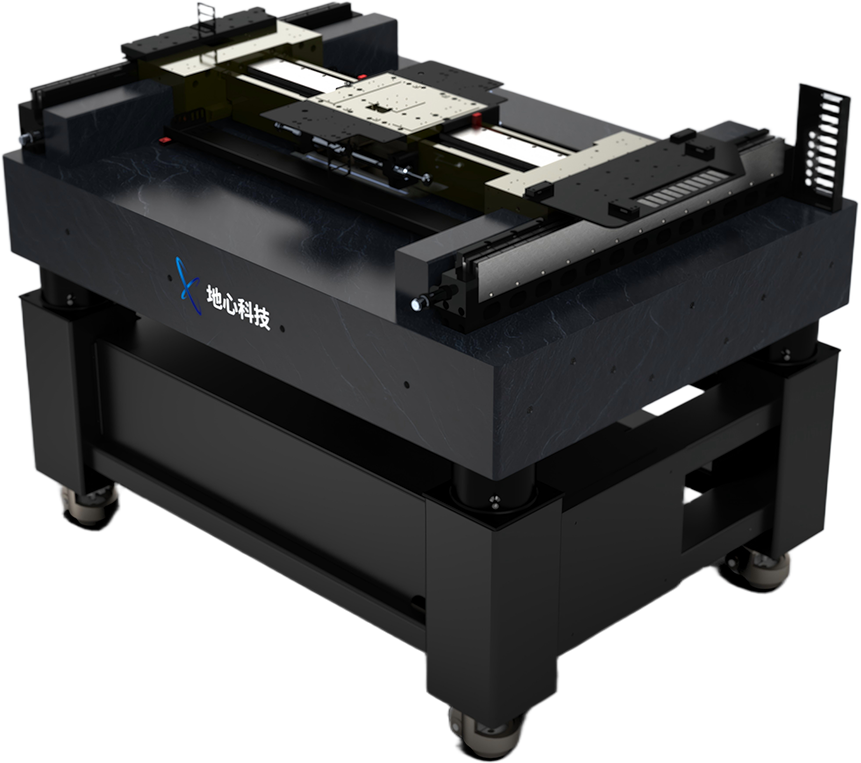
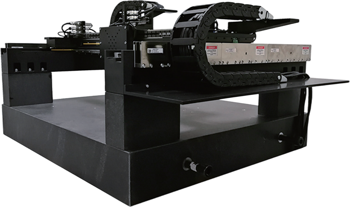
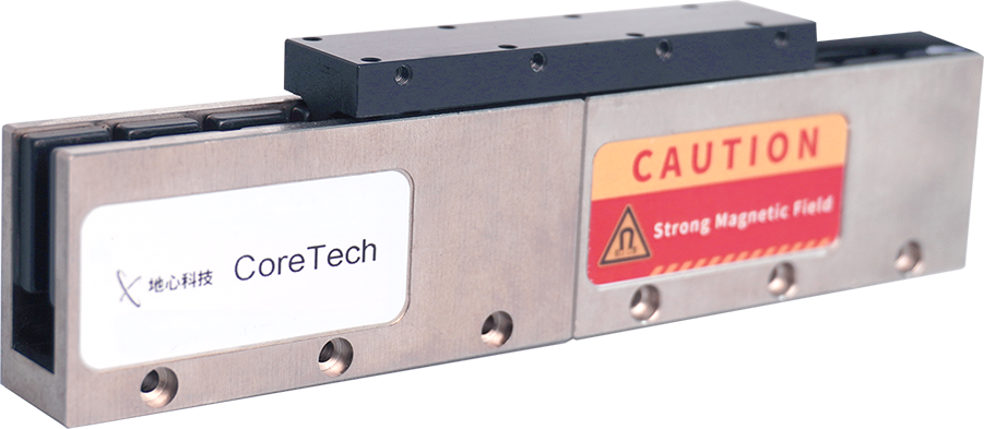
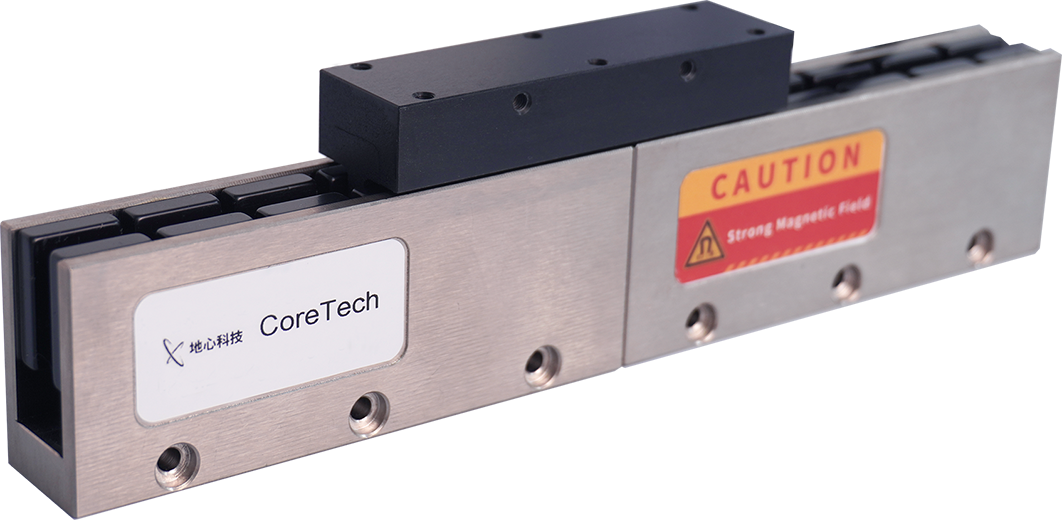
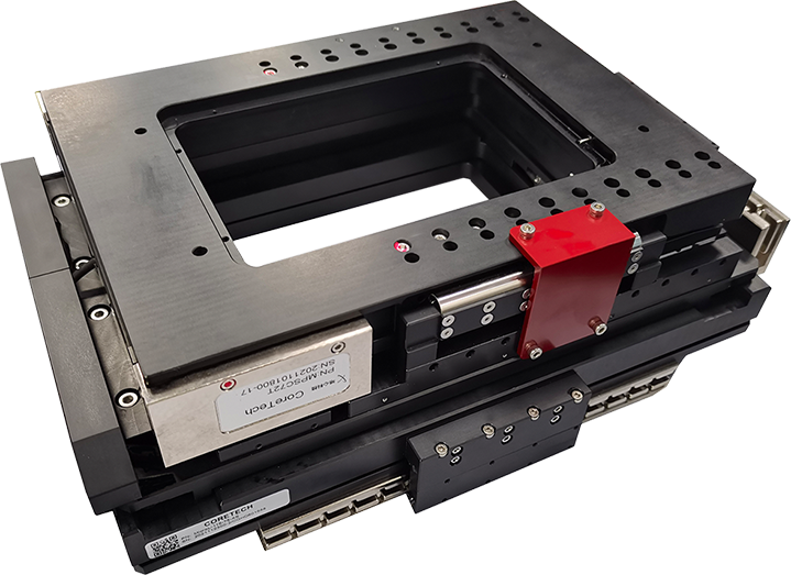
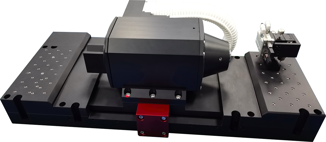
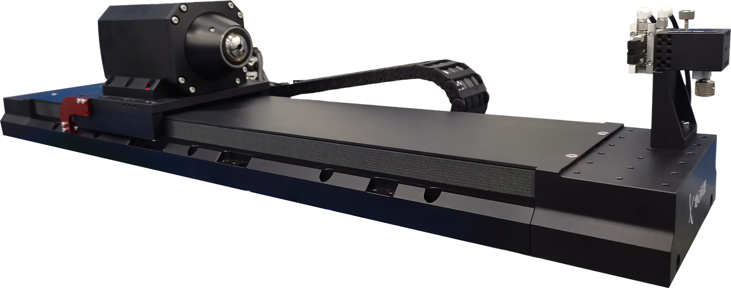
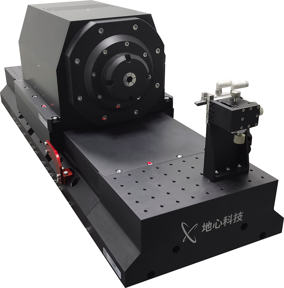
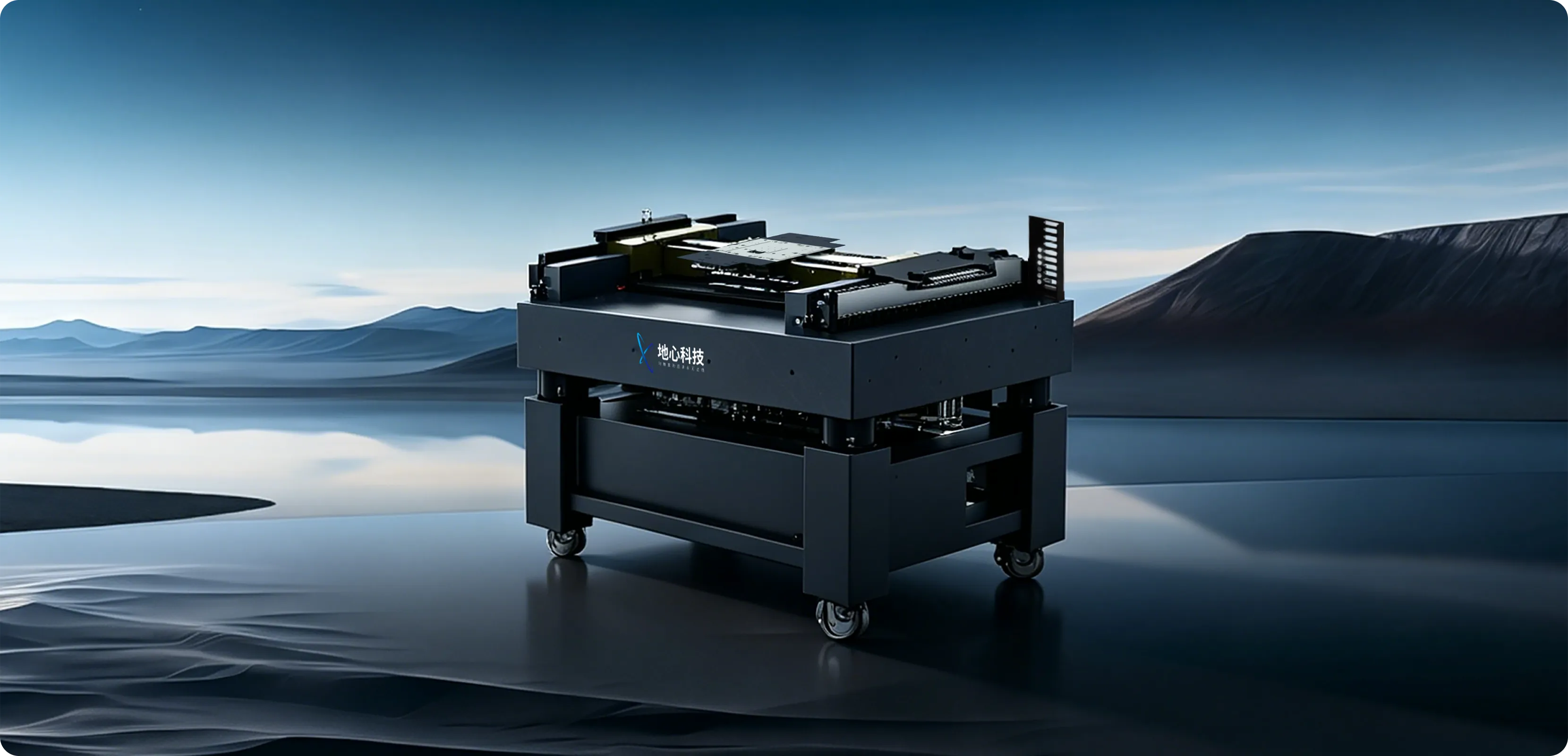
By using a linear-motor-driven mechanical stage as the linear axis, paired with a linear-motor-driven air-bearing rotary stage as the rotational axis, combined with Coretech's proprietary motion control algorithms and ACS motion drive/control modules, this task is accomplished seamlessly.
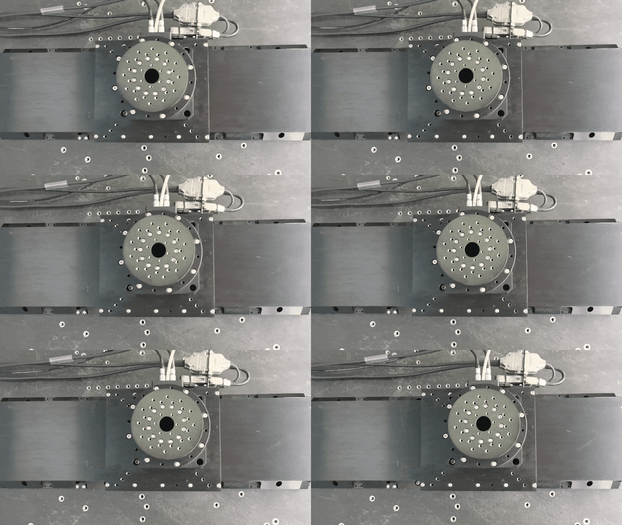
Spiral motion
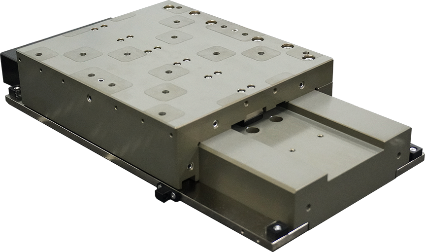
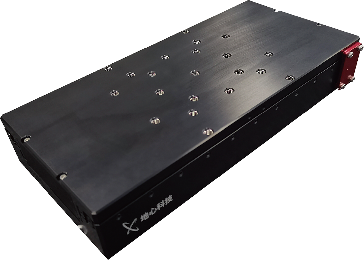
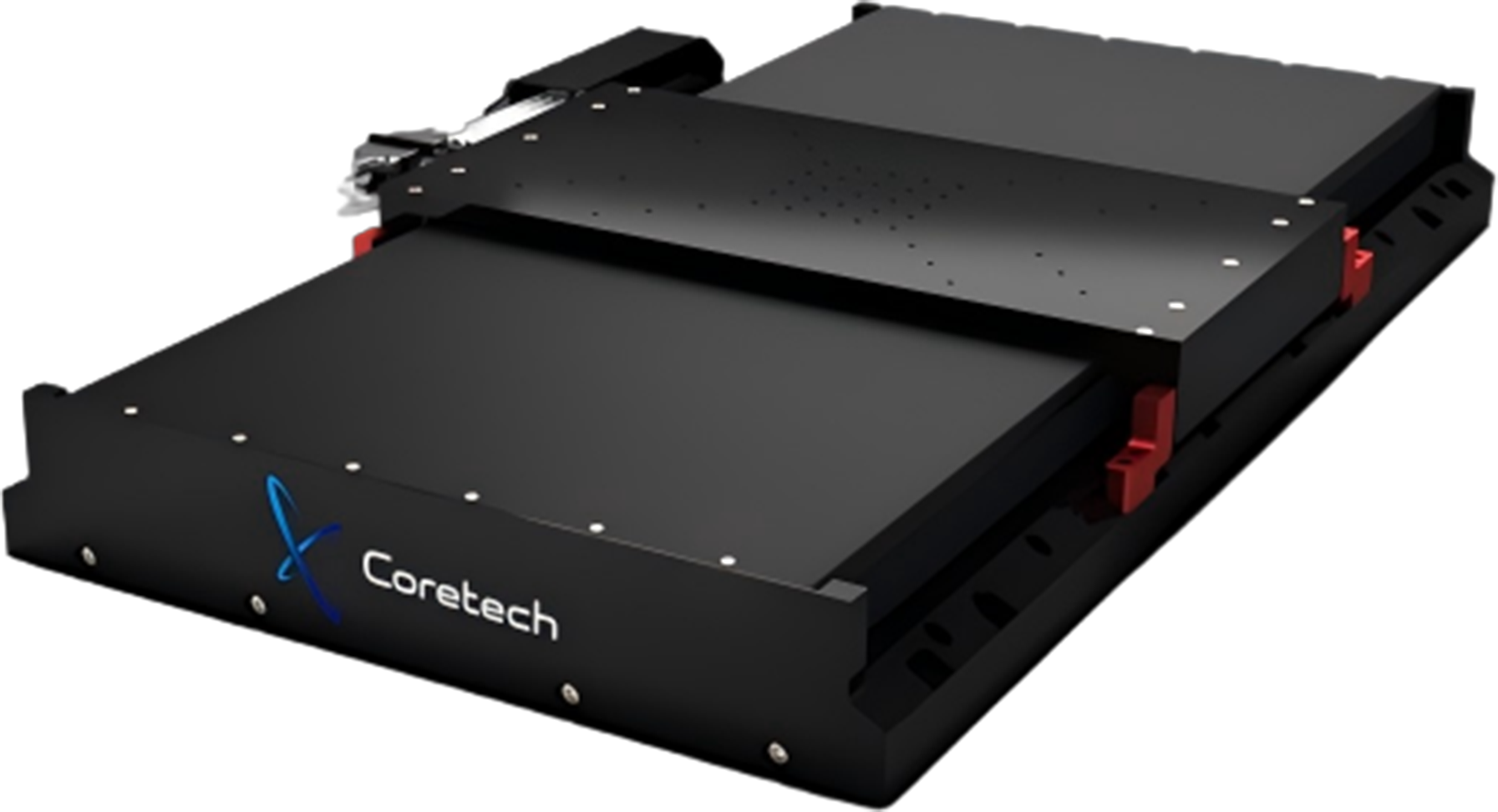
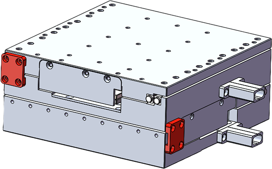
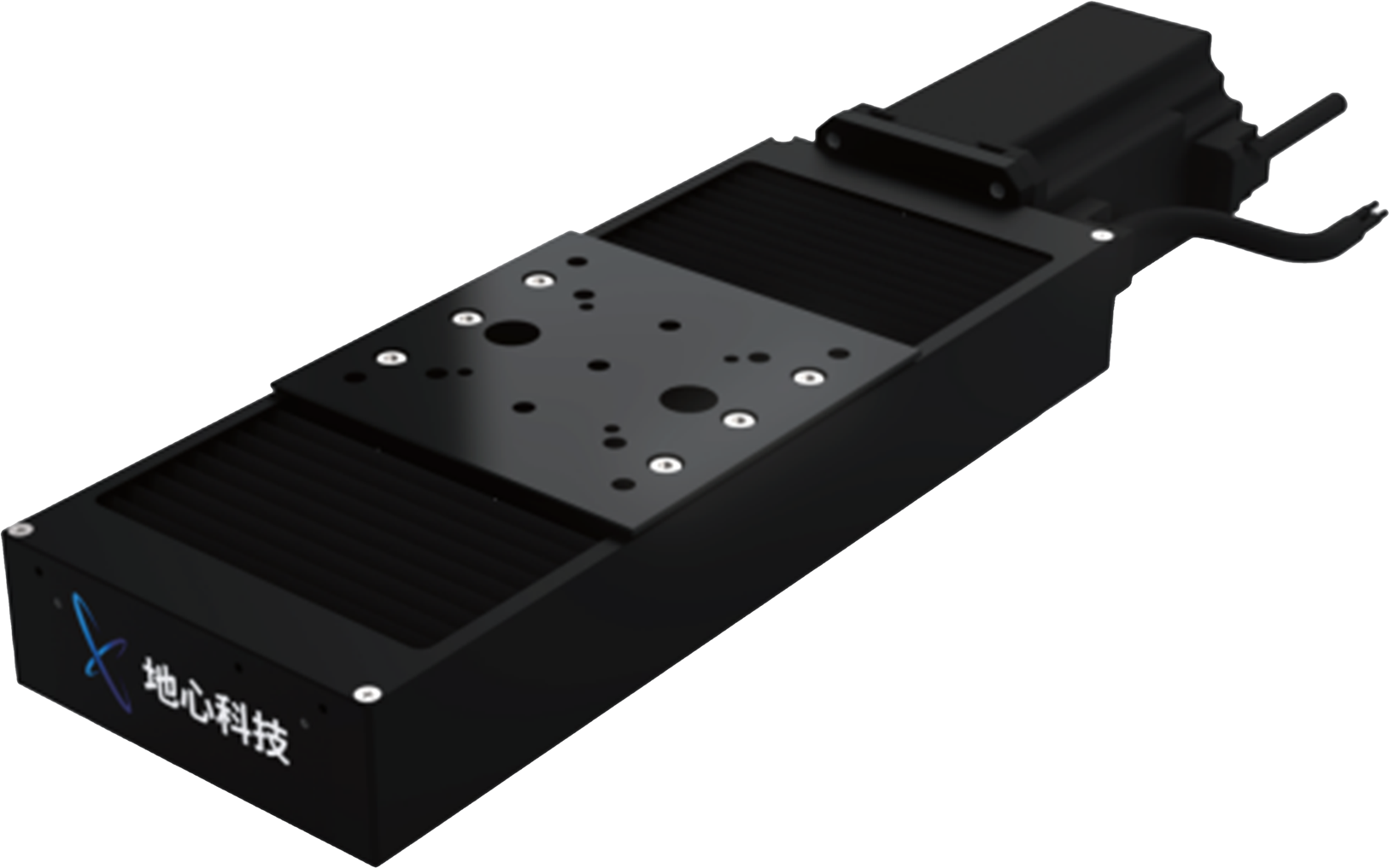
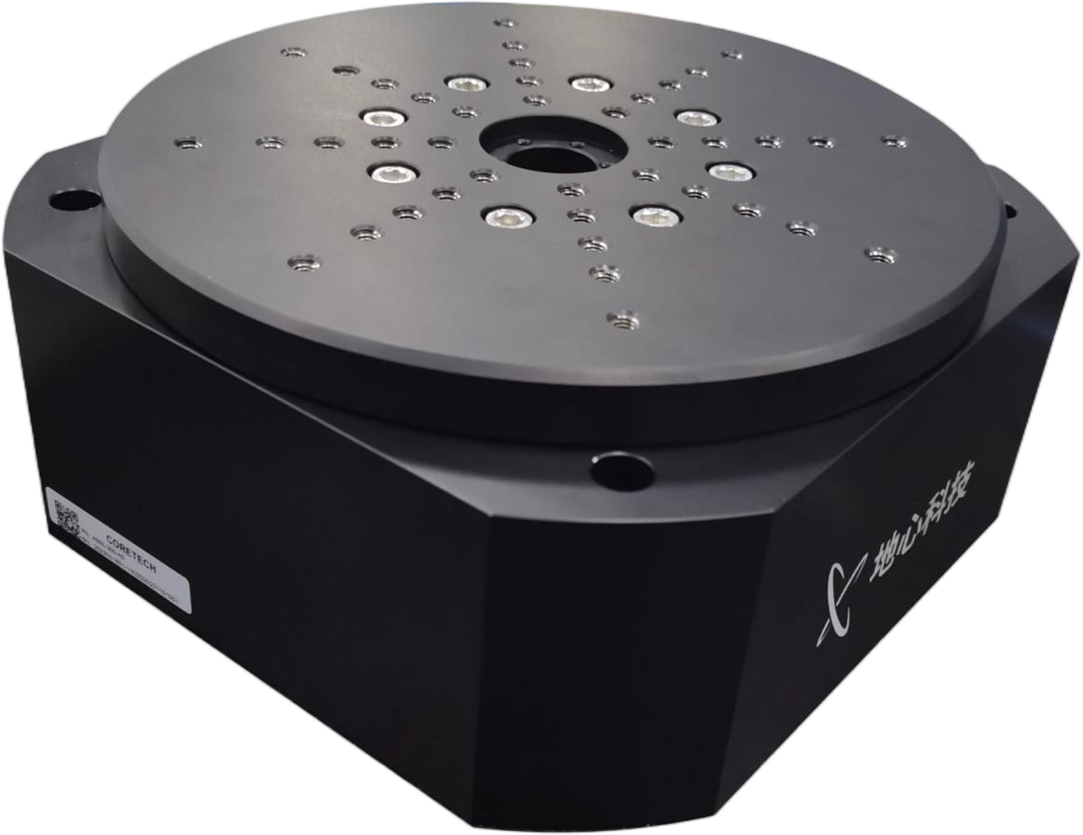
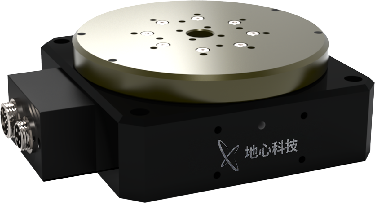
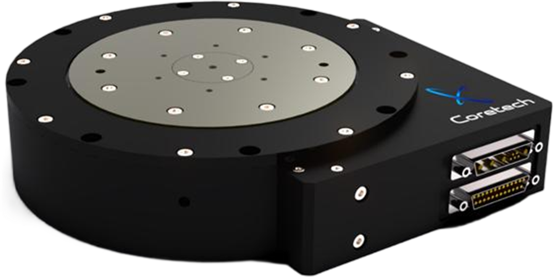
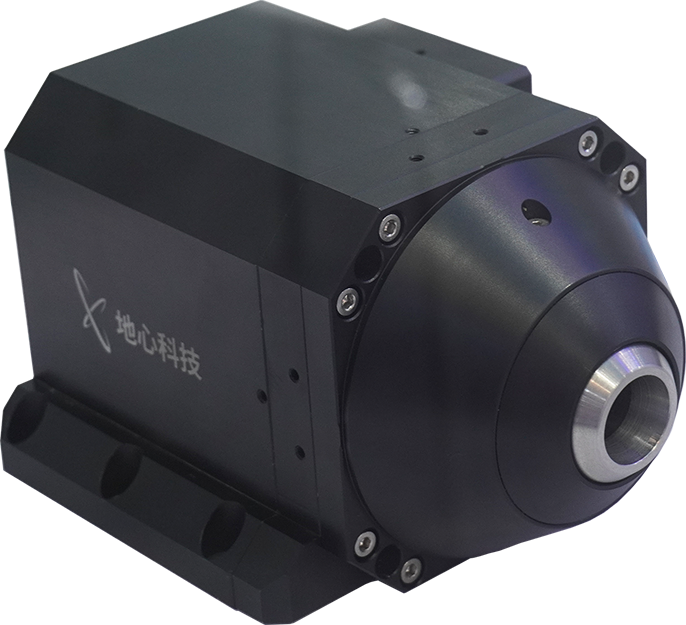
The rotary axis employs Coretech's RAB series high-precision air-bearing direct-drive rotary stage. The RAB series utilises Coretech's self-developed circular direct-drive motors, achieving no-load speeds exceeding 1500 rpm, with customised versions reaching up to 5000 rpm. The RAB series features direct-drive rotary motor control, delivering outstanding dynamic performance and positioning accuracy. The standard tabletop diameter is 150 mm, with other sizes available upon request. Equipped with high-precision circular grating position feedback, it achieves positioning accuracy better than 1 arc second, with axial and radial runout of less than 250 nm—exceptional mechanical performance that makes it highly suitable for wafer defect inspection applications.
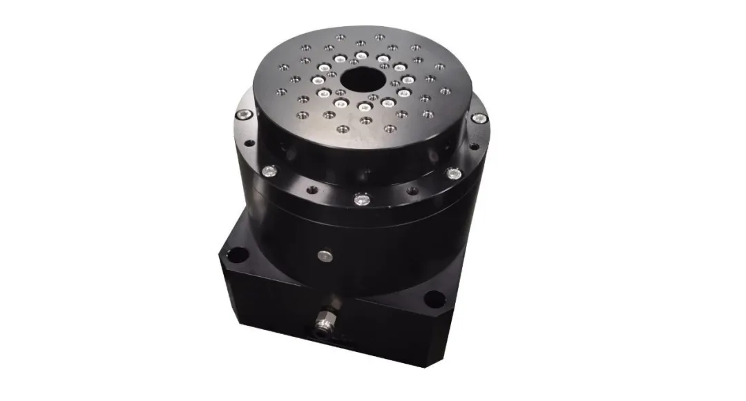
RAB series high-precision air-bearing direct-drive rotary stage
| 载物台直径: | 150mm; |
| 转角误差: | ≤±1.5 arc sec; |
| 重复性: | ≤±0.75 arc sec; |
| 轴向误差: | 同步误差<250nm, 异步误差<20nm; |
| 径向回转误差: | 同步误差<250nm, 异步误差<20nm; |
| 最小步进量 | 0.75 arc sec; |
| 最高转速 | 1500rpm(可定制5000rpm) |
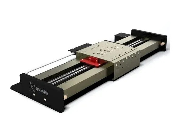
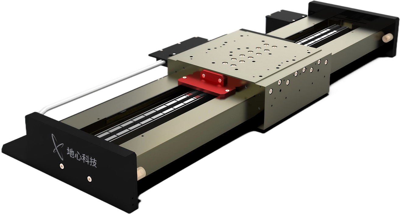
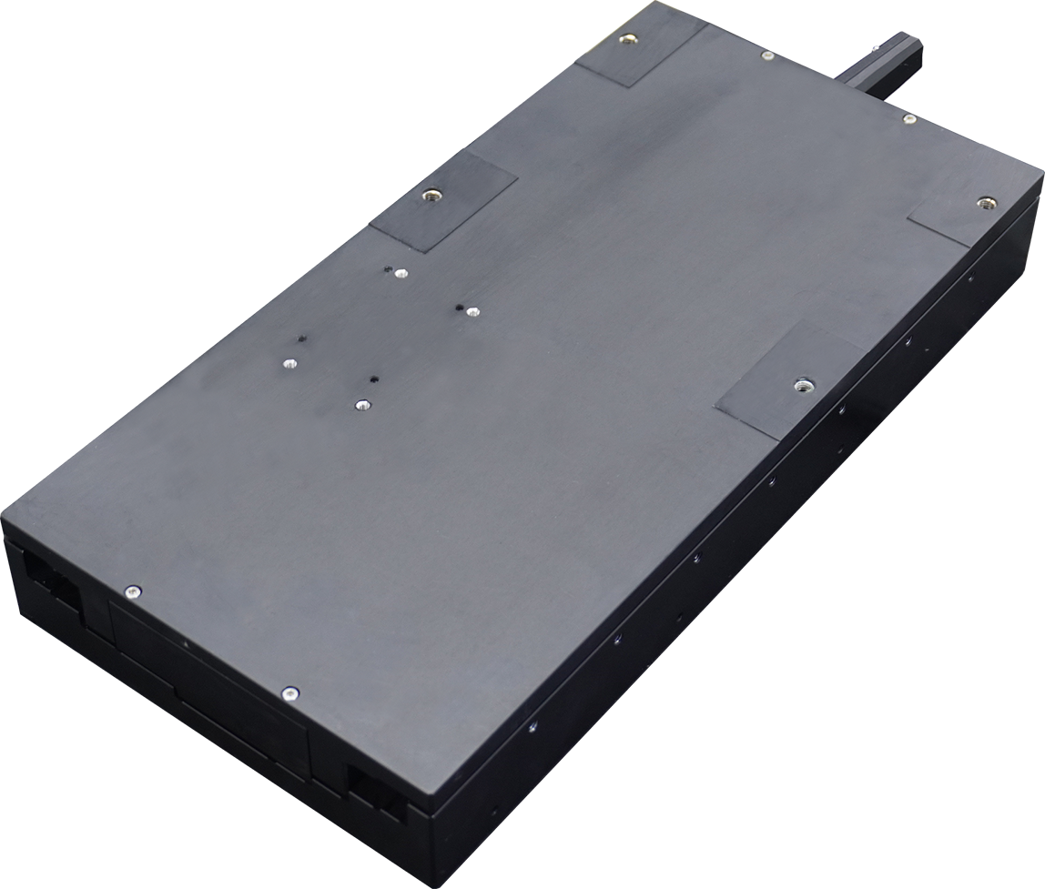
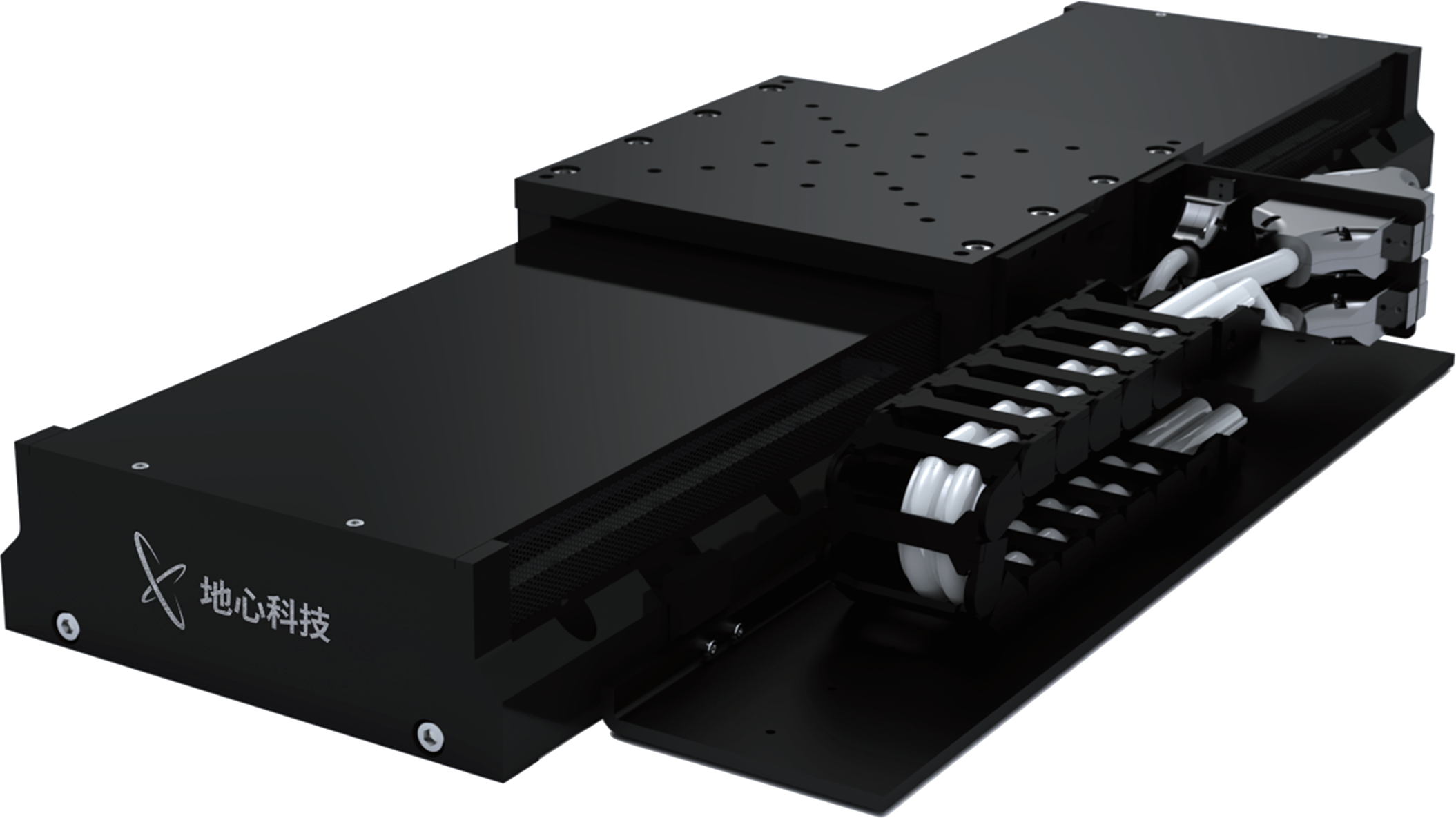
LAB210-200 high-precision air-bearing direct-drive stage
| 有效行程: | 200mm |
| 定位精度: | ≤±0.3μm |
| 重复定位精度: | ≤±0.1μm |
| 最大负载(水平安装): | 35kg |
| 在位稳定性: | ≤±10nm |
| 最小步进量: | 10nm |
05 Going a Step Further for User Convenience
To make the system even more user-friendly, we have developed a dedicated spiral-path tool software. With simple configuration, the motion mechanism can generate the motion path and automatically produce the corresponding trigger points as required. Additionally, we provide a dynamic link library (DLL), enabling users to easily integrate the entire system into their own measurement systems.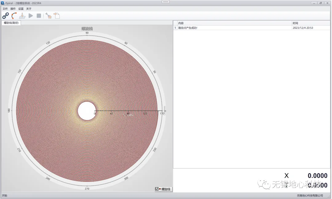
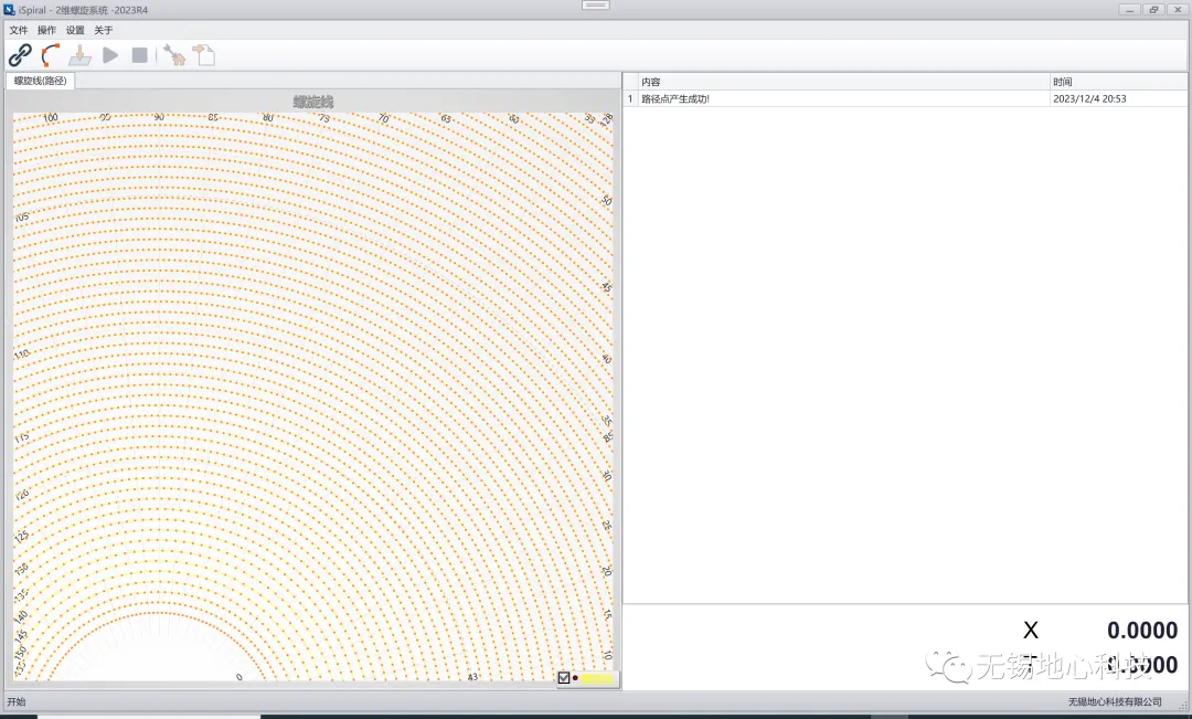
Spiral path planning software
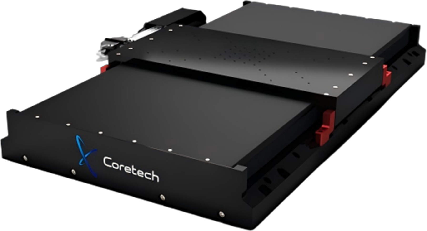
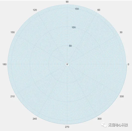
Using Coretech's SMH225LM high-precision direct-drive linear stage and RAB series high-precision air-bearing rotary stage, together with the spiral path planning software, scanning from a spiral radius of R=160 down to R=4, the entire inspection process takes only approximately 47 seconds. During the entire process, the maximum dynamic error of the Theta axis in the constant-velocity segment is less than ±0.003°, and the maximum dynamic error of the X-axis in the constant-velocity segment throughout the full scan is less than ±0.5 μm.
测试轨迹
Featured News
High-Precision Motion Stages Enhancing Coupling Alignment Accuracy in Precision Fiber Coupling Equipment
2026.06.03
Improving Yield and Efficiency: High‑Precision Motion Stages Empowering Innovation in Laser Direct Writing Technology
2026.06.03
ASP Series Ultra‑High‑Speed, High‑Precision Air‑Bearing Rotary Stage – Maximum Speed 5000 RPM
2026.06.03
 Back to List