

.png)

.png)







Home
 News Center
The Super Cycle of the Optical Fiber Industry Has Begun: Why Does Fiber Inspection Rely Even More Heavily on High-Precision Motion Stages?
News Center
The Super Cycle of the Optical Fiber Industry Has Begun: Why Does Fiber Inspection Rely Even More Heavily on High-Precision Motion Stages?
News Center
The Super Cycle of the Optical Fiber Industry Has Begun: Why Does Fiber Inspection Rely Even More Heavily on High-Precision Motion Stages?
The Super Cycle of the Optical Fiber Industry Has Begun: Why Does Fiber Inspection Rely Even More Heavily on High-Precision Motion Stages?
 2026-04-28
Share:


01 From Scale Advantage to Technology Leadership – Fiber Quality May Become the Decisive Factor
Specialty optical fiber G.657.A2 has surged 650% in price over the past year, with global orders flooding in—the optical fiber industry has clearly entered a super cycle of rising volume and prices.
As computing power demand skyrockets, the market's need for high‑quality optical fiber has become unprecedentedly urgent. AI data centers are driving a significant increase in the density of high‑specification fiber usage. The three major scenarios—Scale‑up (intra‑rack interconnection), Scale‑out (inter‑rack interconnection), and DCI (Data Center Interconnection)—all rely on large volumes of high‑quality optical fiber.
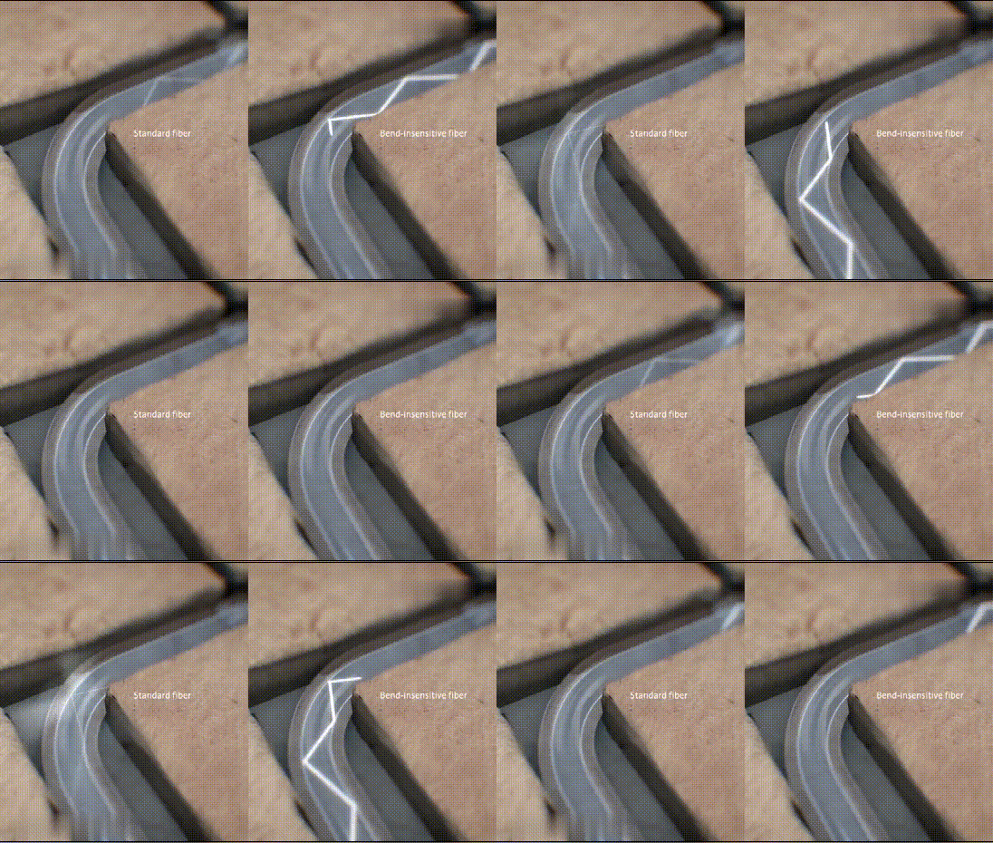
The cladding diameter of a standard communication fiber is typically 125 μm, and after coating, the outer diameter is commonly 245 μm or 250 μm. In high‑density cabling and transmission systems, a single optical cable often integrates multiple fibers. For such a fine and precise transmission medium, any tiny scratch, stain, or end‑face defect can, during connection, bending, vibration, or long‑term service, cause increased insertion loss, deteriorated return loss, and consequently compromise link stability.
Beyond demand growth, industry competition is also shifting from pure price competition to comprehensive competition centered on product quality, stability, and consistency.
02 The Rigorous Quality Examination – How Strict Are the "Physical Examination" Standards for a Single Fiber?
Fiber inspection is a core step in the optical communications industry to ensure production quality and link performance. The inspection scope typically covers multiple aspects, including geometric parameters, optical performance, surface defects, and connector end‑face conditions.
1. Geometric Parameter Inspection
Geometric parameter inspection is used to ensure fiber‑to‑fiber coupling efficiency and is a mandatory factory‑exit test item. Inspection metrics include cladding diameter (standard single‑mode fiber nominal 125 μm, tolerance ±0.7 μm), core diameter (single‑mode nominal 9 μm, tolerance ±0.5 μm), core‑cladding concentricity error (≤0.5 μm), non‑circularity (core ≤3%, cladding ≤2%), and warp (≤0.5°).
In practice, white‑light interferometers and digital holographic microscopes are commonly used to image the fiber end‑face/sidewall, and the parameters are calculated via image processing algorithms. The general requirement for the repeatability positioning accuracy of the inspection stage is ≤ ±200 nm to ensure measurement consistency and imaging stability.
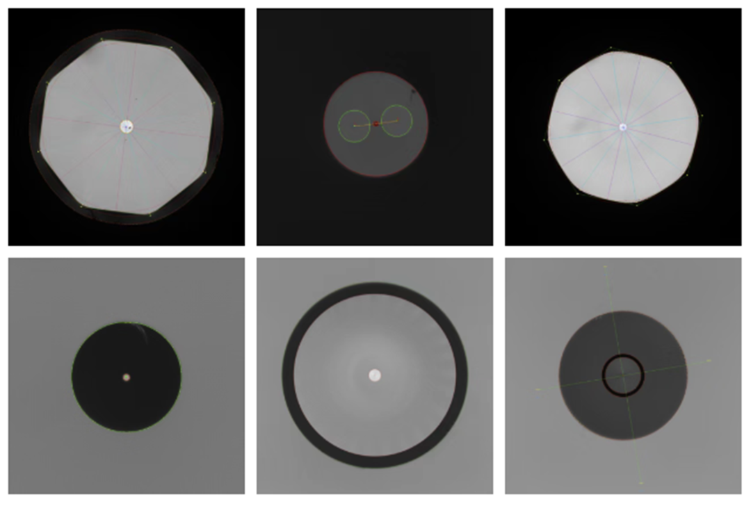
(Image source: Wuhan Juhe Photonics – fiber test result images)
2. Optical Performance Testing
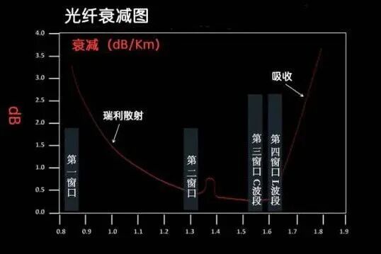
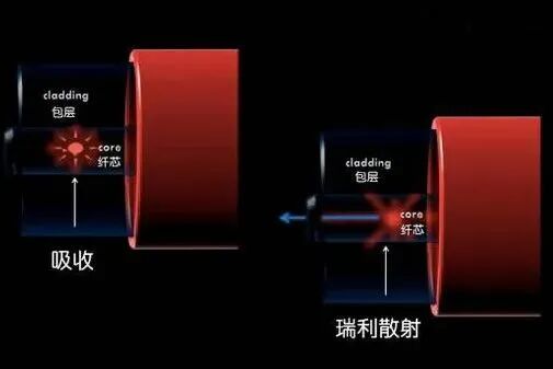
Optical performance testing is used to verify the signal transmission capability of the fiber, covering manufacturing, testing, and operation/maintenance stages. Among these, attenuation testing relates to power loss during optical signal transmission, while dispersion testing directly affects waveform preservation and bit‑error performance in high‑speed signal transmission.
In such high‑precision testing, motion stages can undertake tasks such as sample positioning, optical path switching, probe or lens scanning, and fine optical path adjustment in some interferometric measurements. Although different test methods have somewhat different requirements for motion control, positioning accuracy, dynamic response, and operational stability all directly affect test efficiency and result repeatability.
3. Surface and Defect Inspection
In addition to the above two categories, identifying physical damage that could affect reliability is also a core inspection item for optical fibers.
Fiber optic connector end‑face inspection is often one of the most easily overlooked yet most likely to cause link problems during testing and installation. Micron‑scale "pits + tilt + alignment errors" can be amplified into significant noise in the system. Therefore, end‑face inspection of fiber optic connectors is extremely important.
According to the International Electrotechnical Commission (IEC) standard 61300‑3‑35, for single‑mode fiber end faces, any scratches or defects in the core zone are prohibited; for multimode fiber end faces, scratches not exceeding 3 μm are permitted, along with a maximum of four defects not exceeding 5 μm. These tiny imperfections, invisible to the naked eye, are precisely the key factors that lead to increased insertion loss, worsened return loss, and elevated link failure risk.
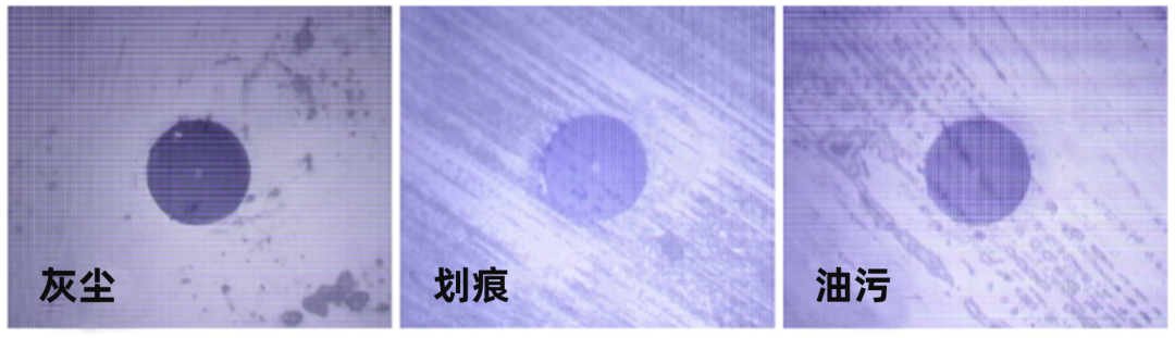
(Illustration of fiber connector end‑face defects)
Although IEC 61300‑3‑35 is primarily aimed at fiber connector end faces, its classification and dimension‑determination logic for scratches and defects are equally applicable to bare fiber end‑face quality inspection.
For more thorough detection of scratches, pits, stains, chipping, and other defects, the inspection system must be capable of identifying scratches with a minimum size ≤0.1 μm, and require dynamic Z‑axis focusing to achieve clear imaging across the entire end face.
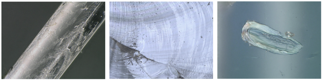
(Image source: Keyence – illustration of fiber surface defects)
03 Addressing the Pain Points of Fiber Inspection – Ground Motion Technology's Solution Supports Industry Quality Assurance
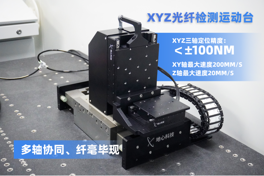
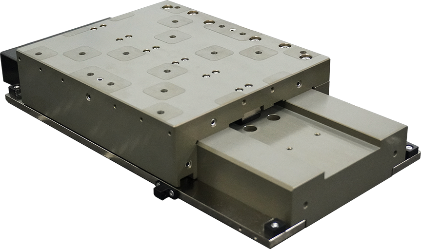
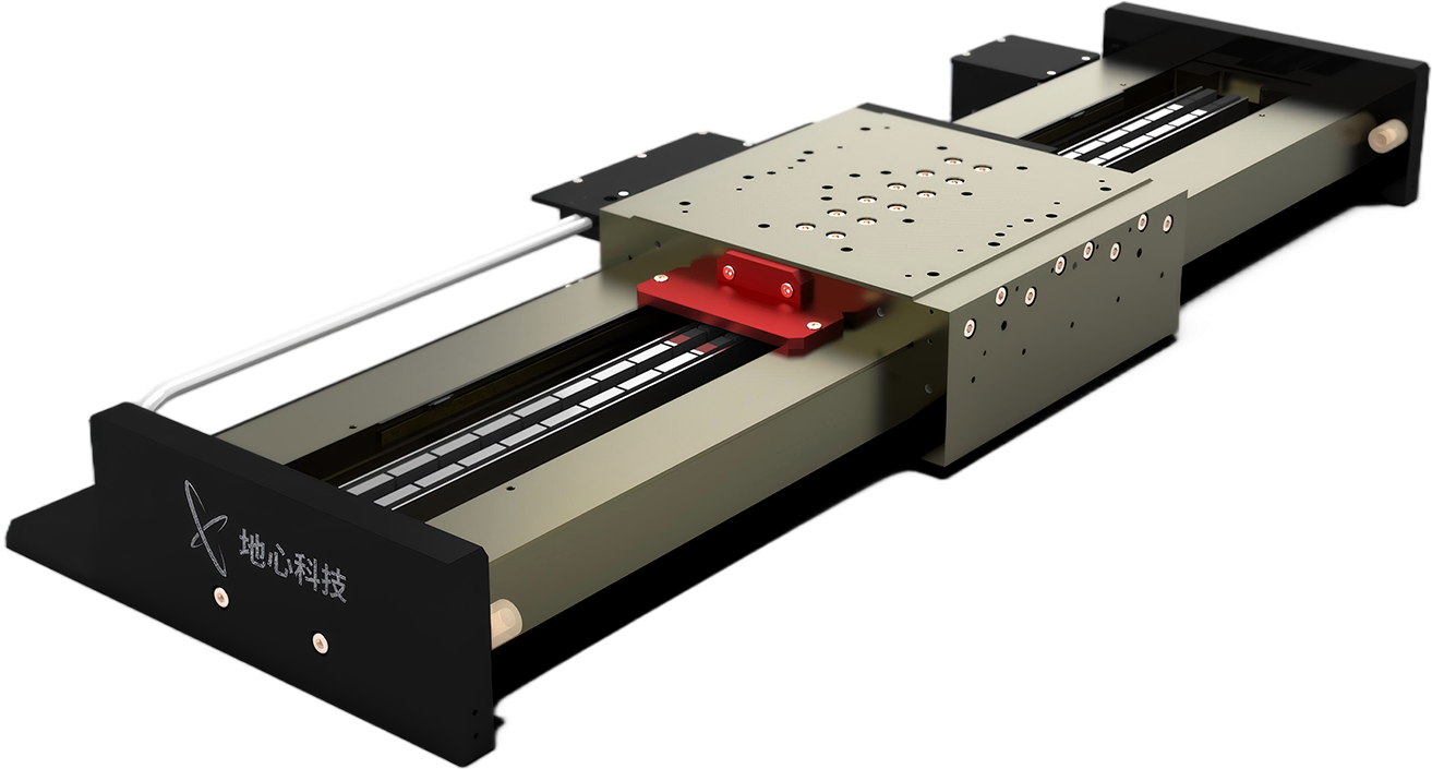
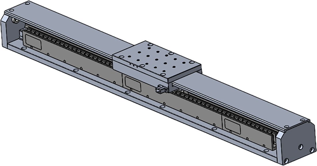
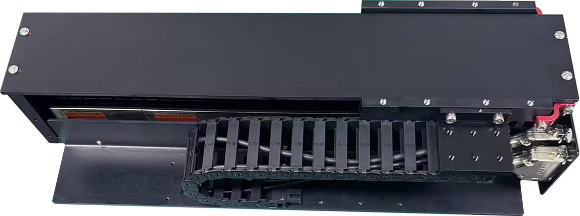
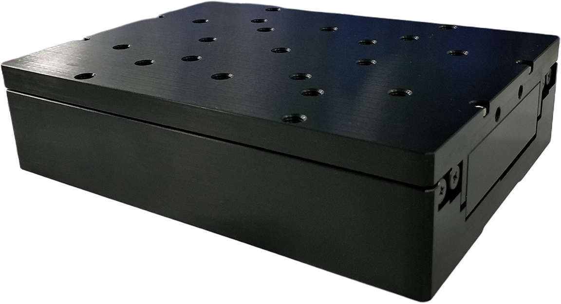
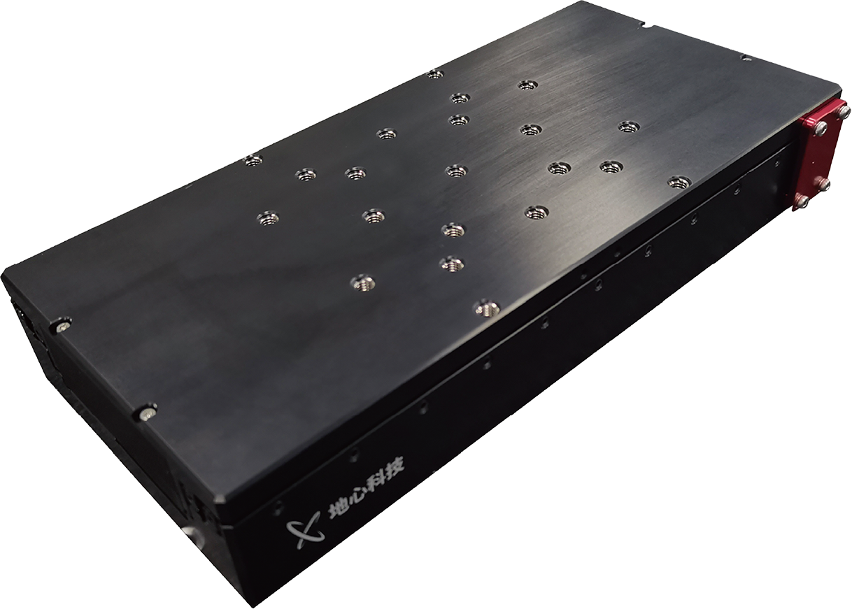
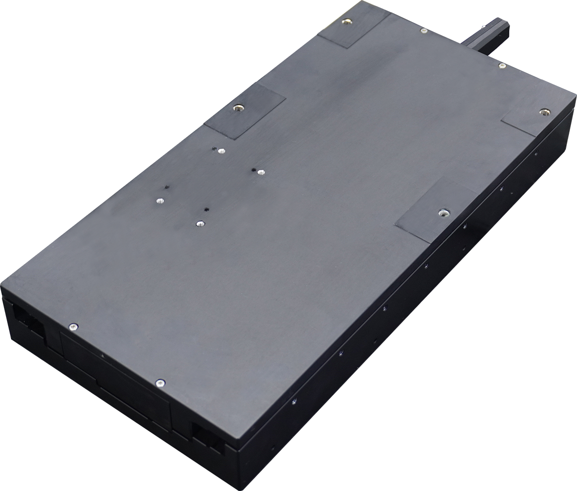
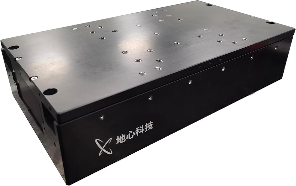
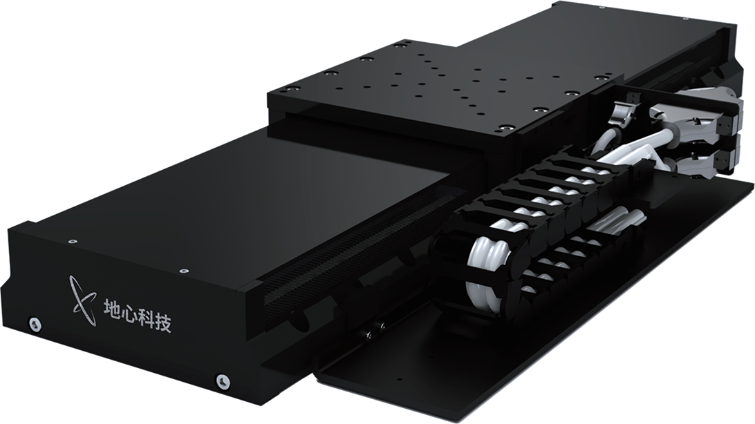
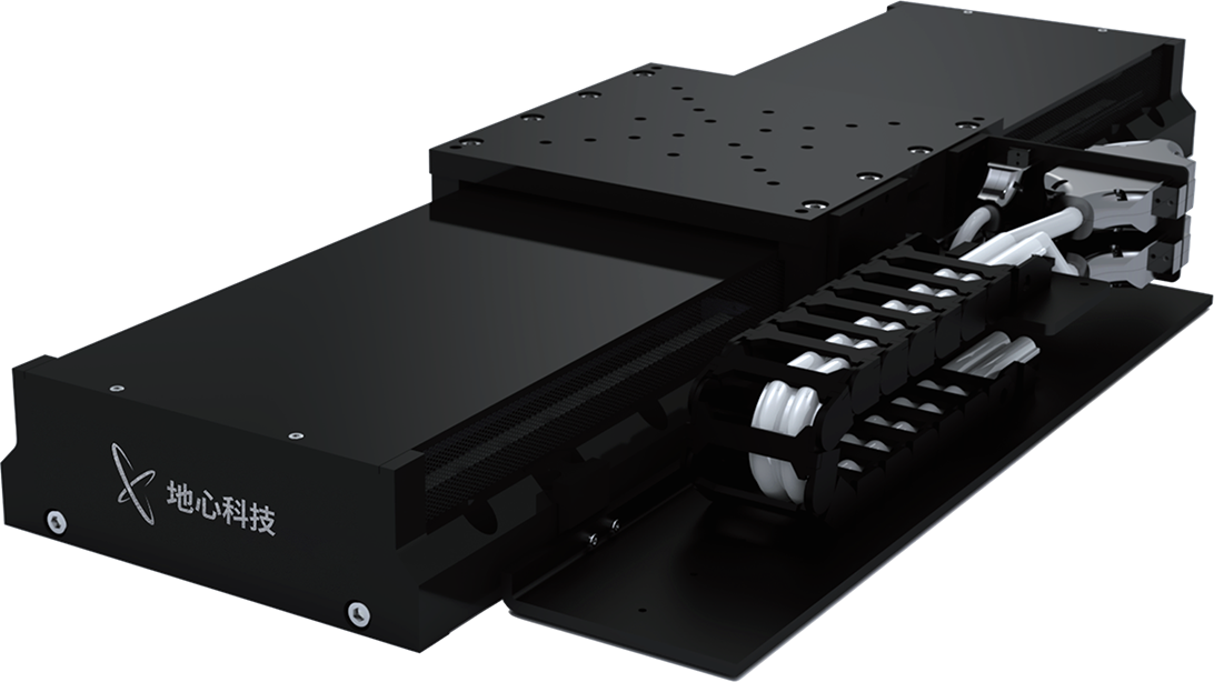
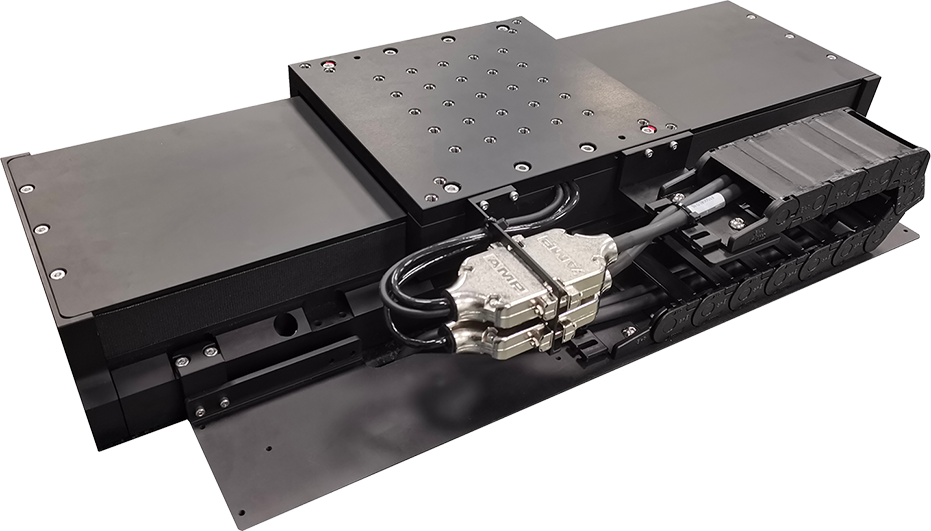
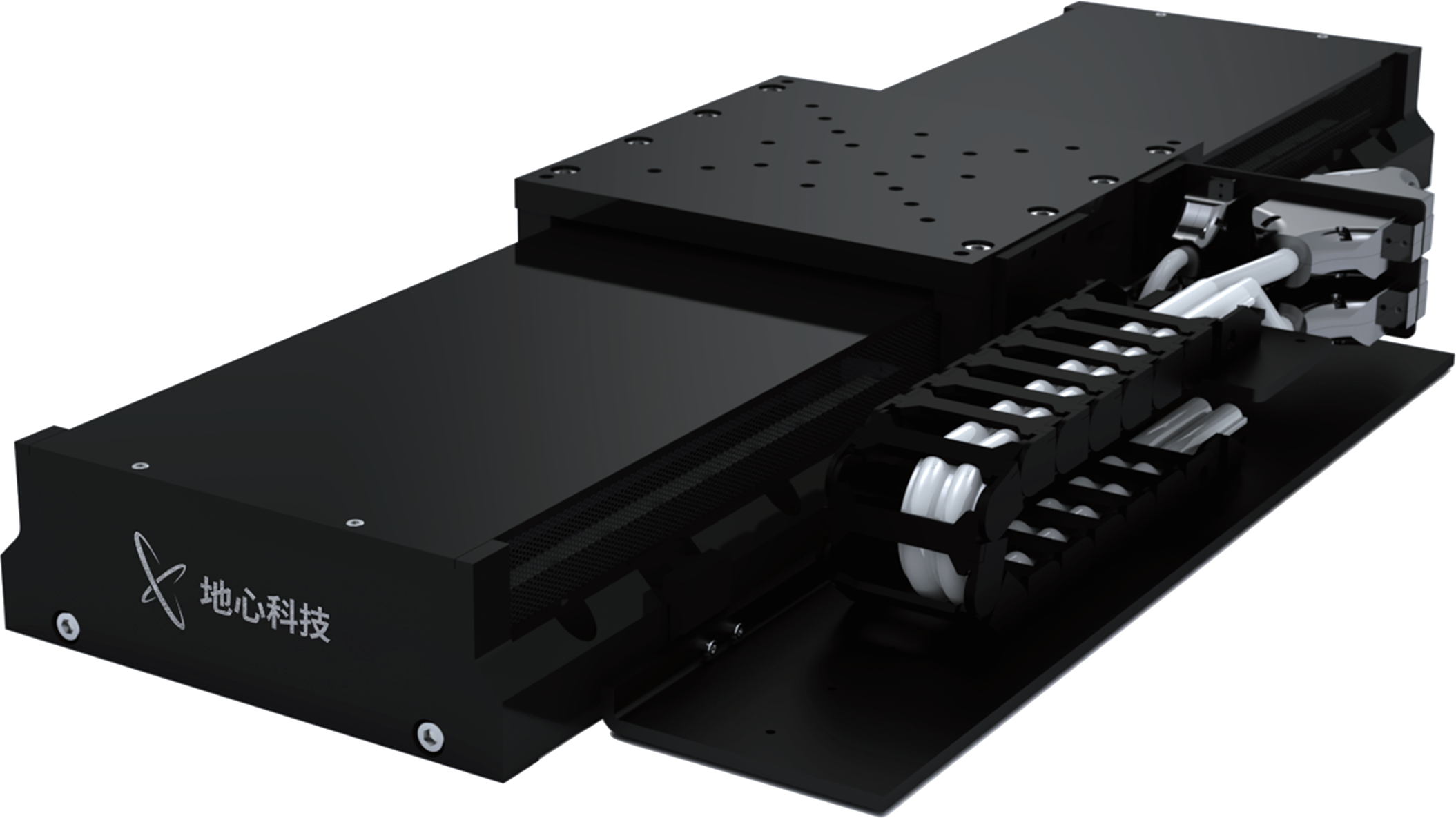
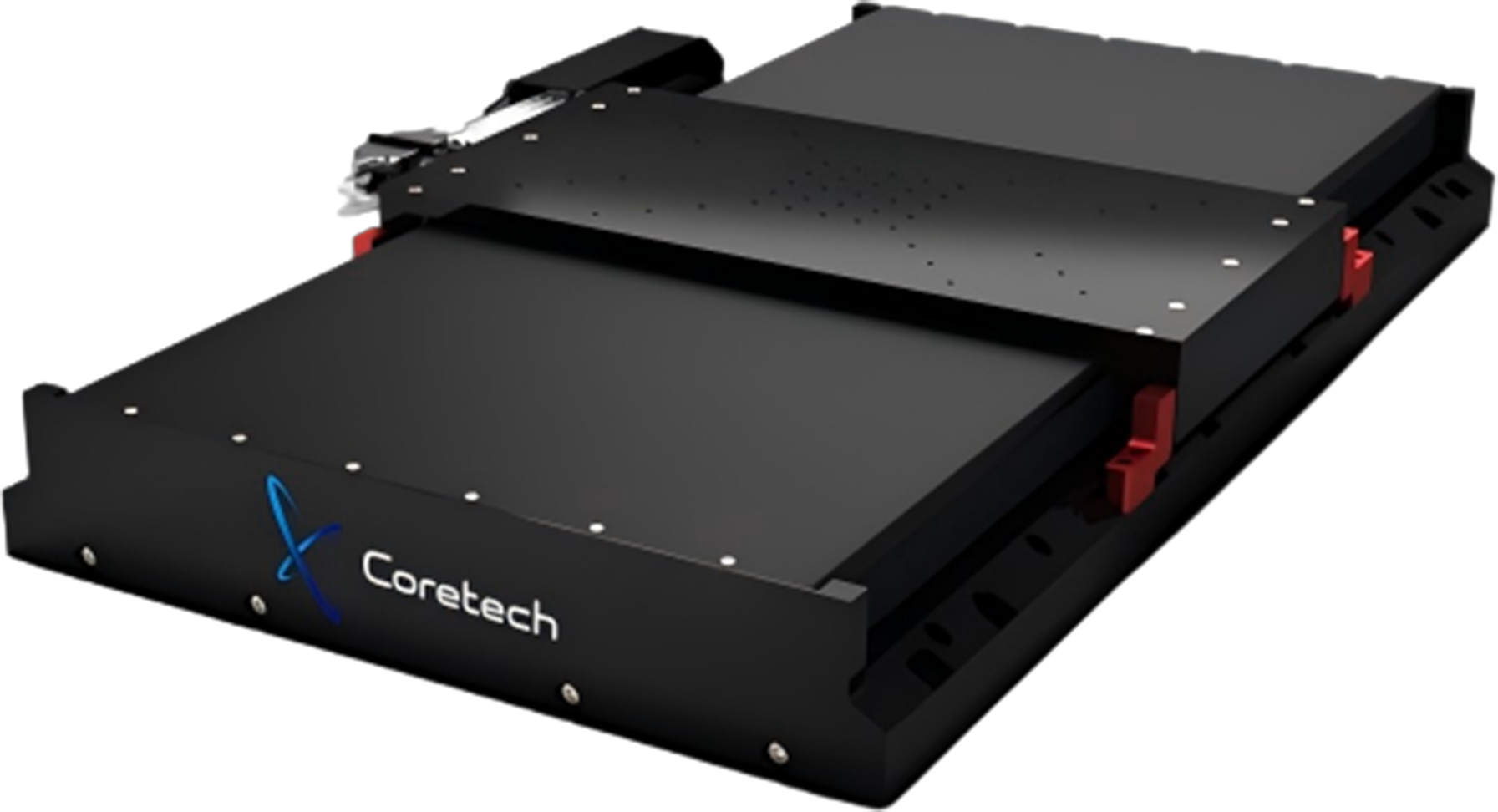
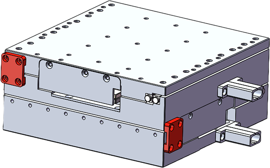
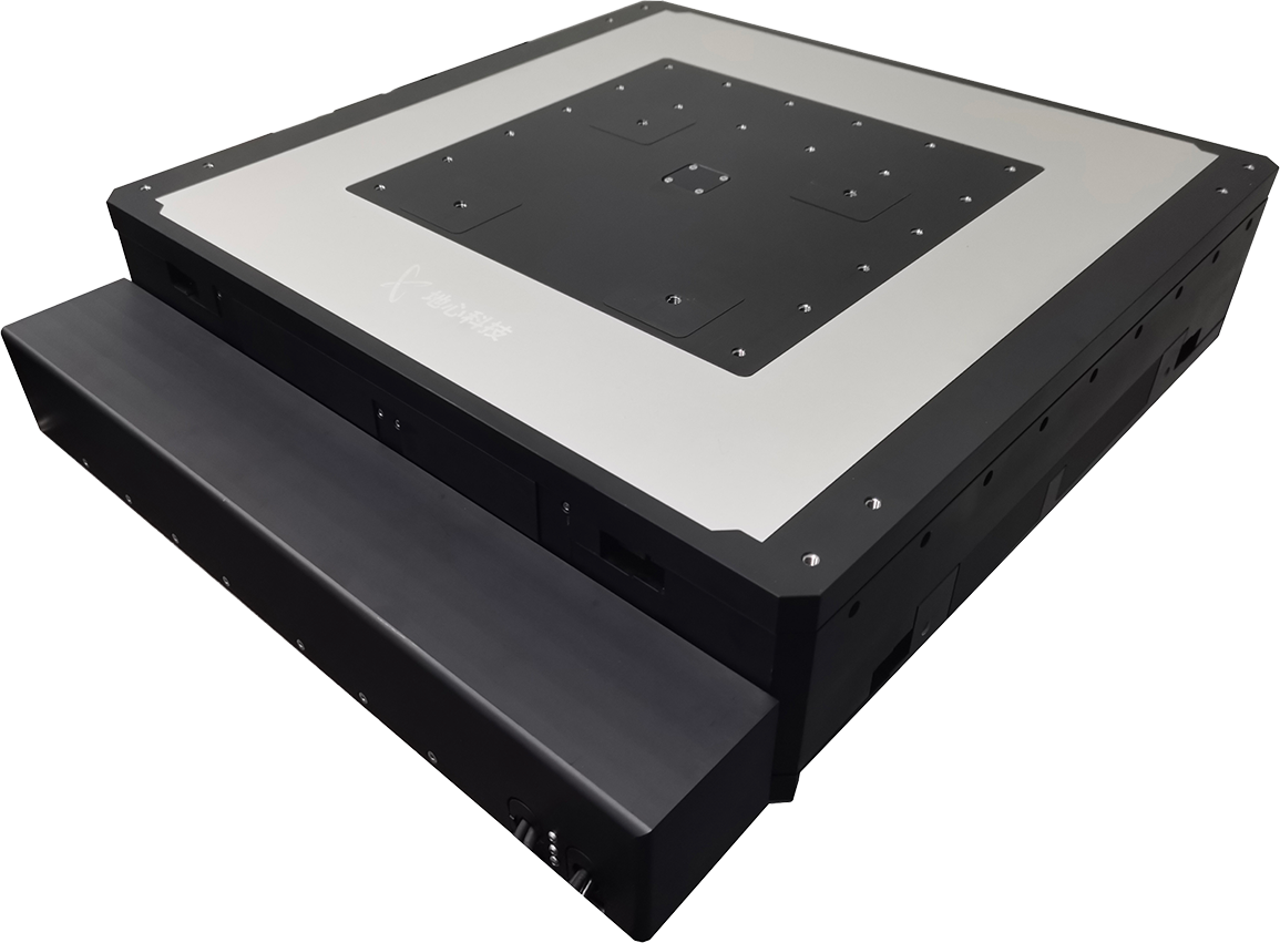
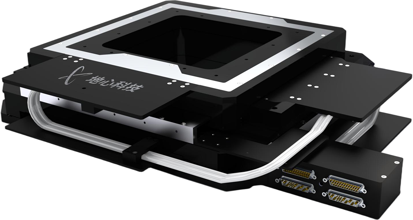
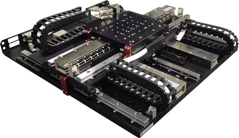
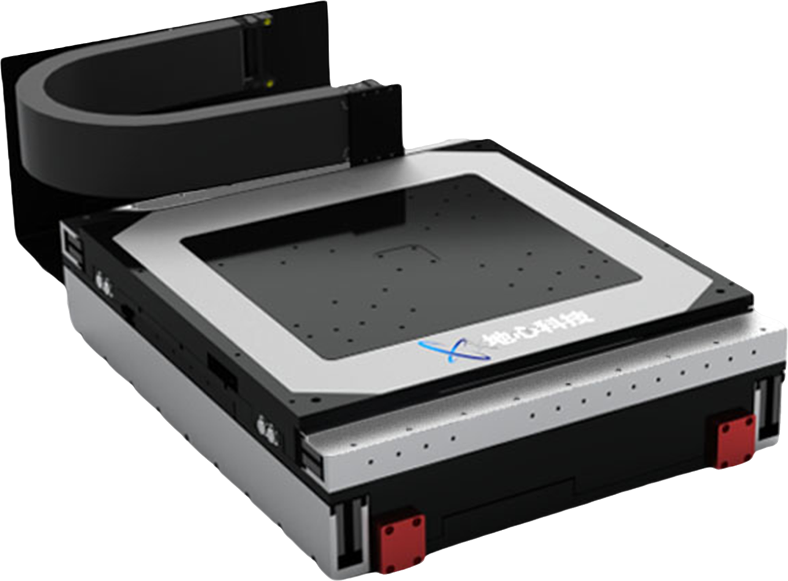
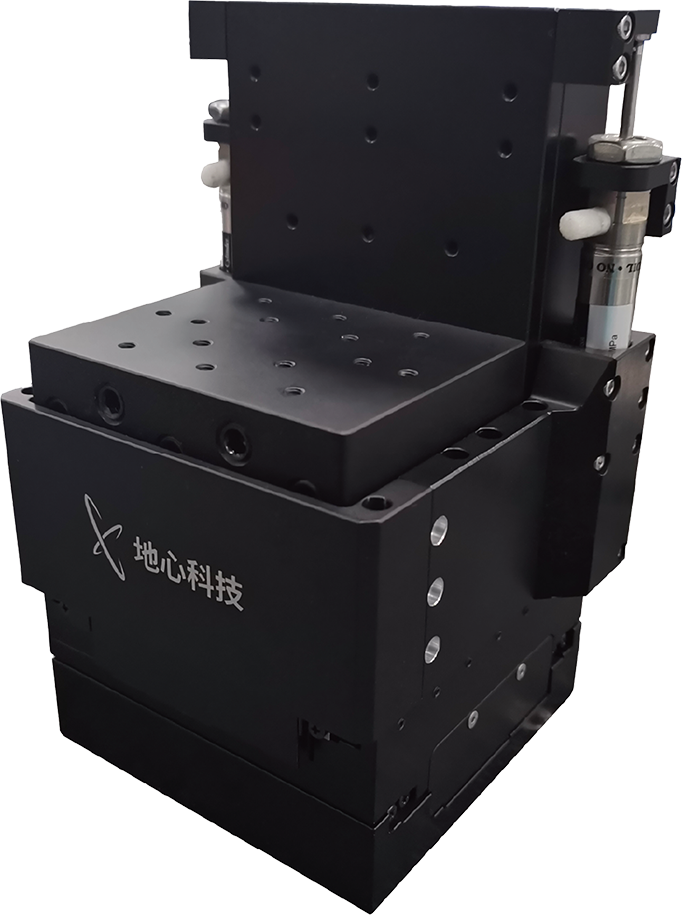
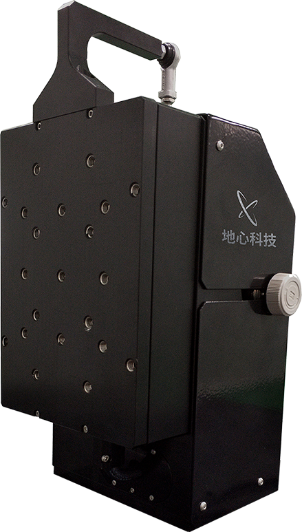
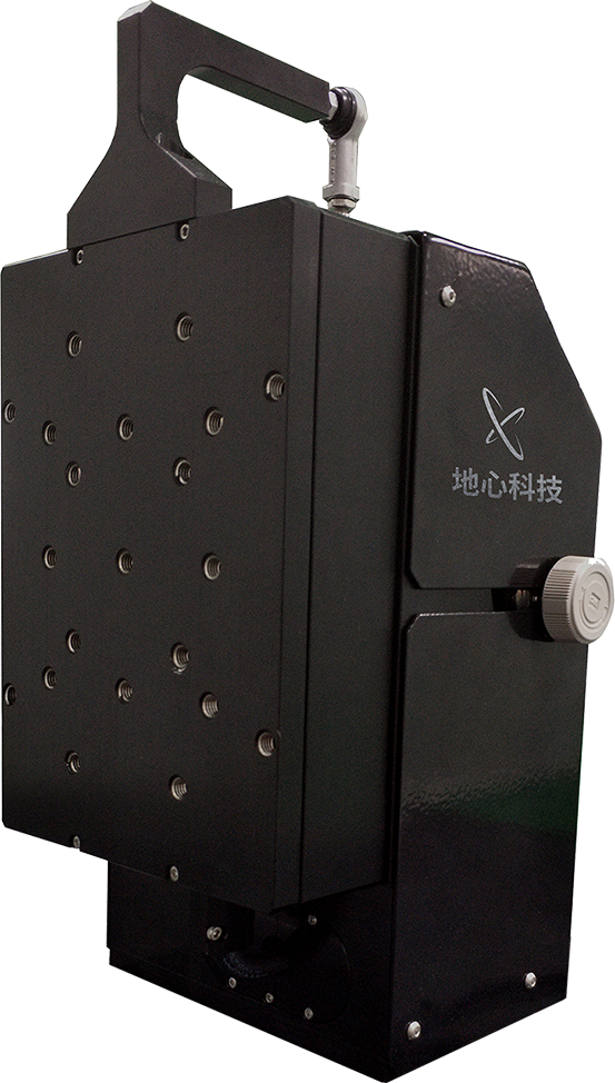
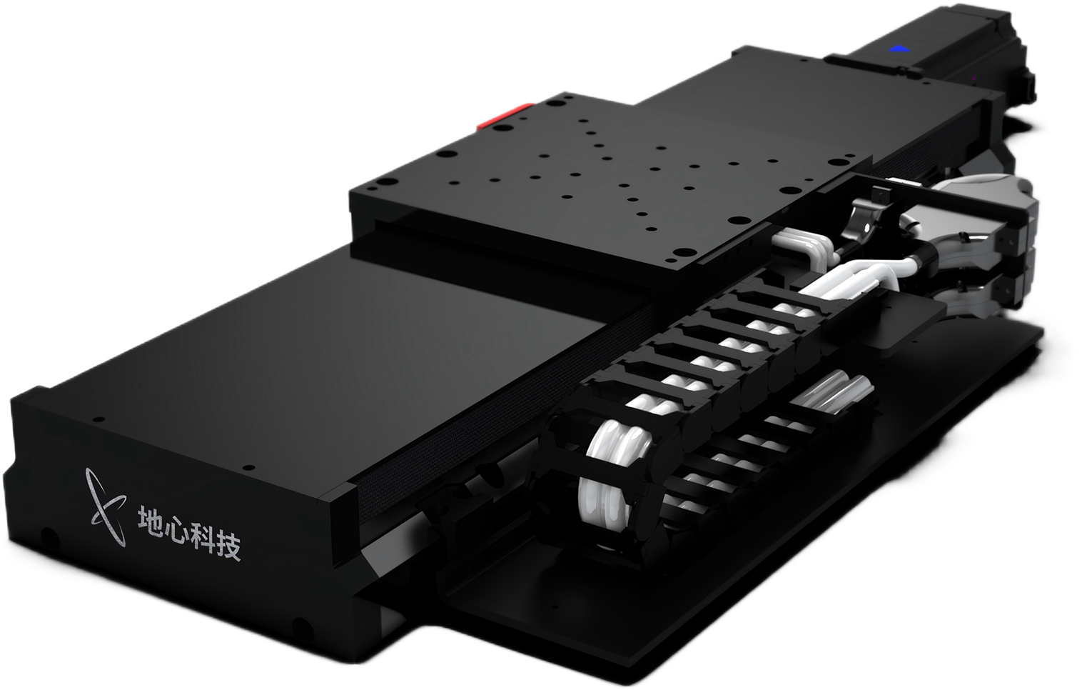
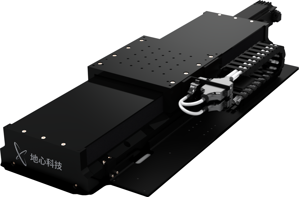
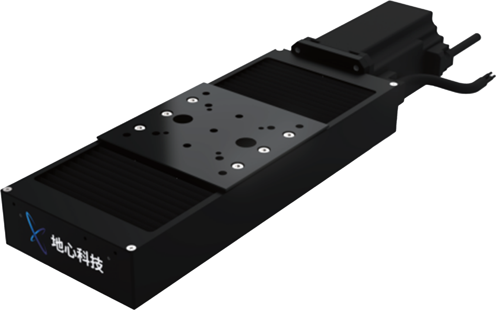
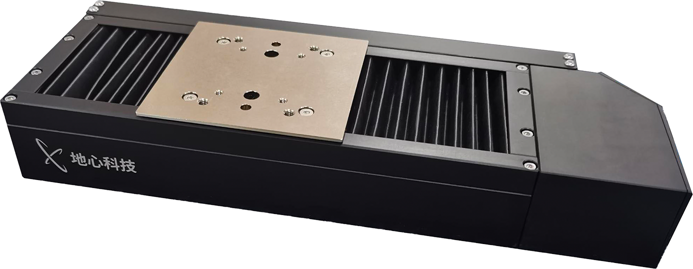
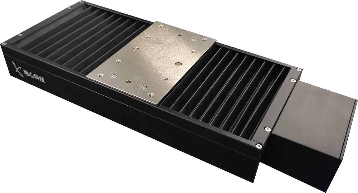
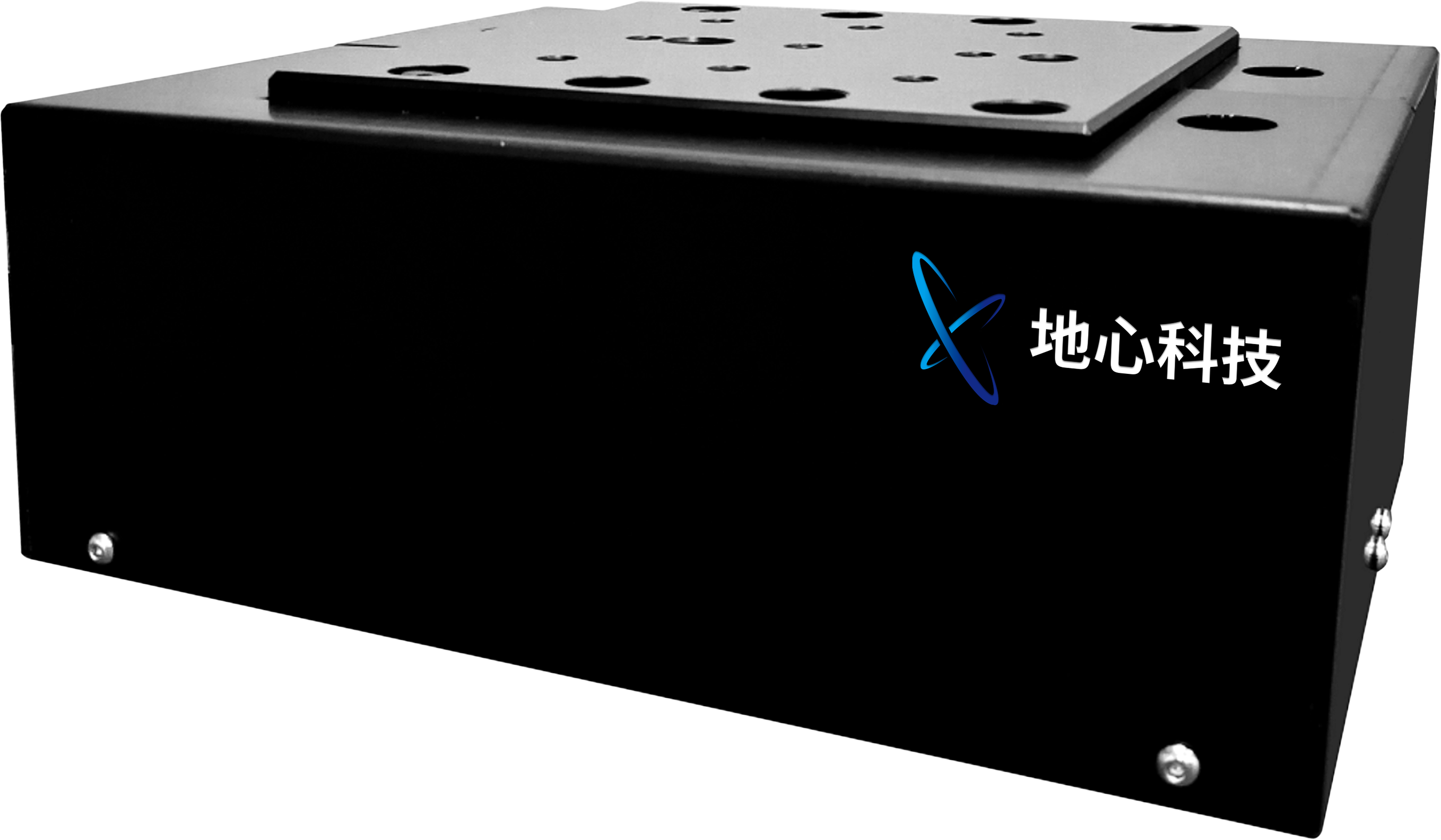
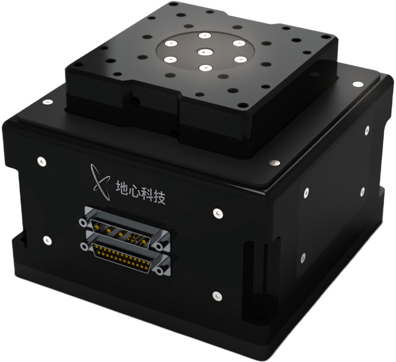
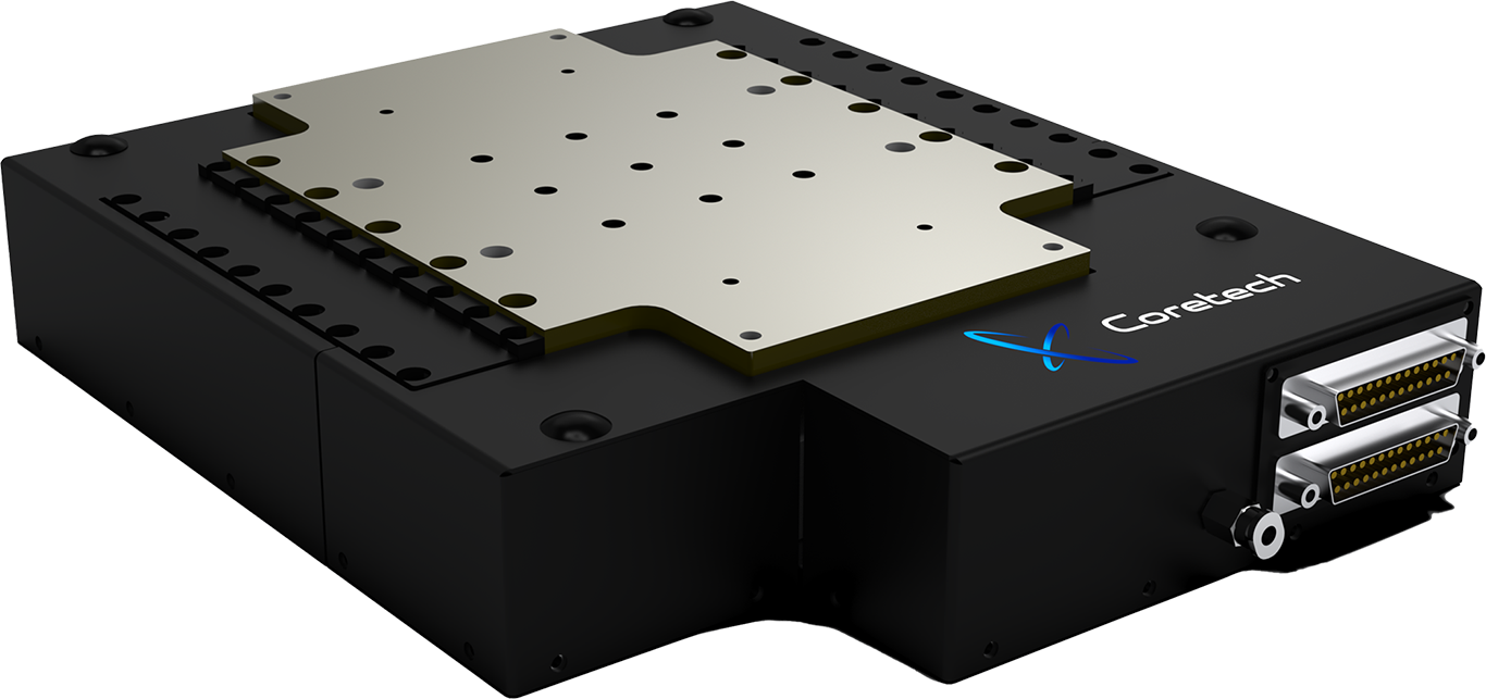
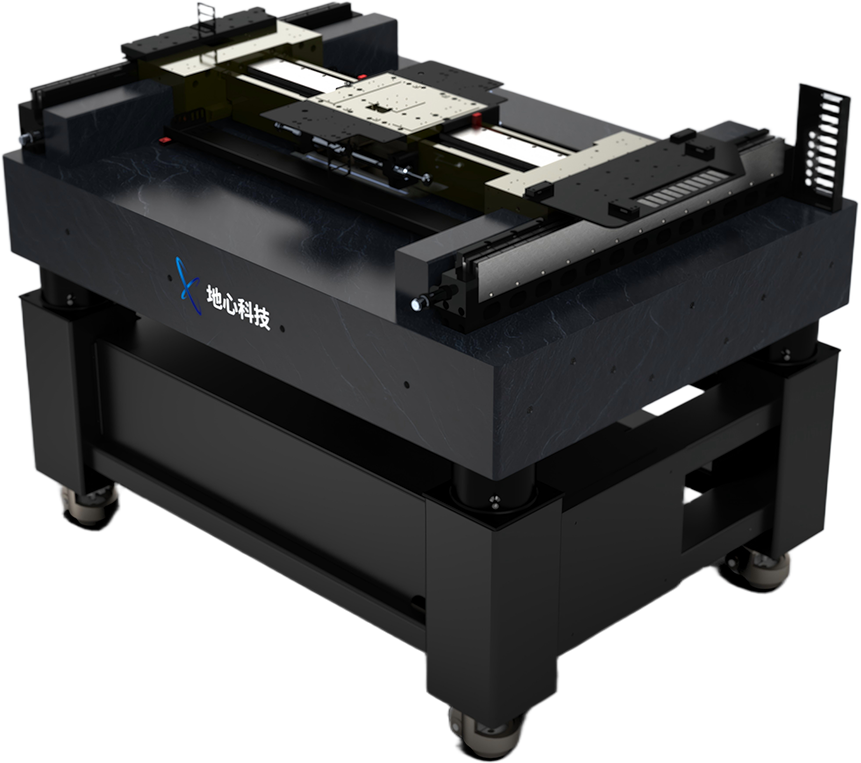
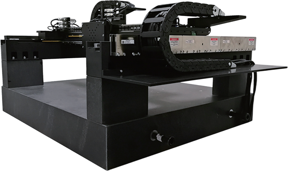
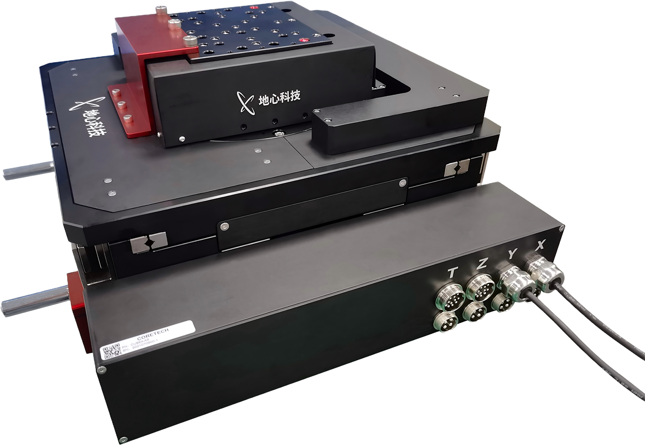
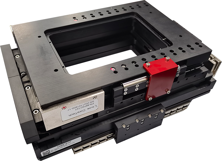
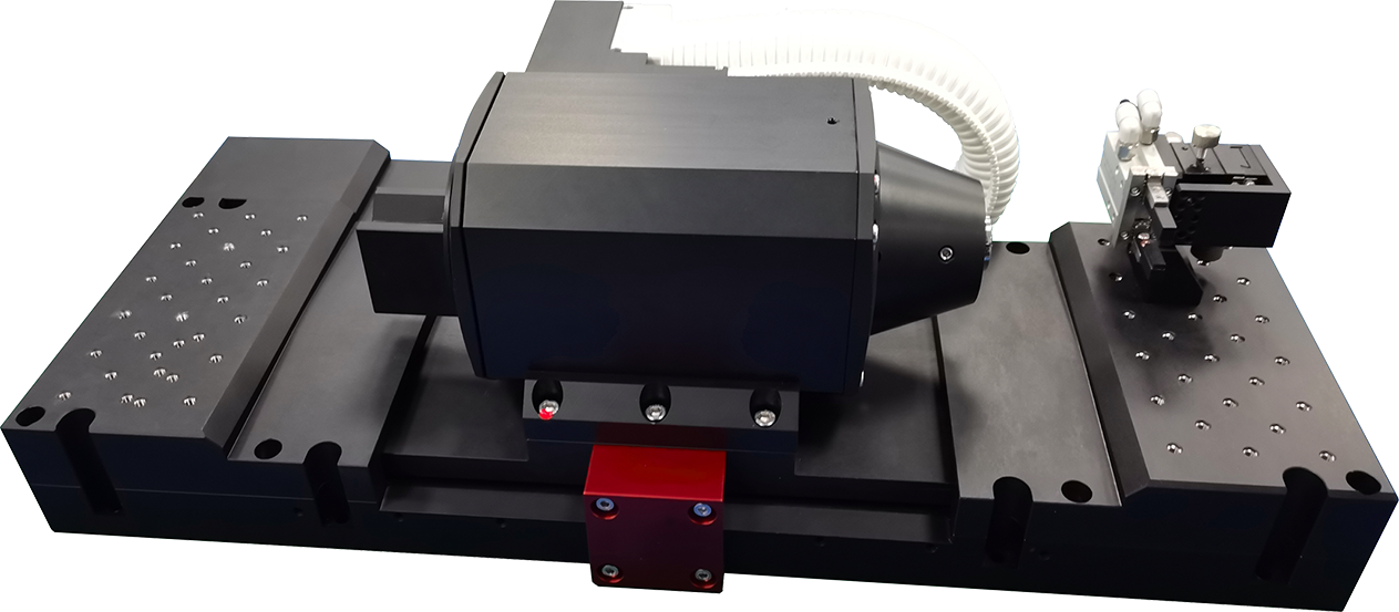
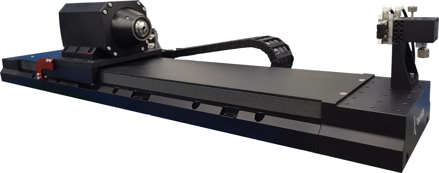
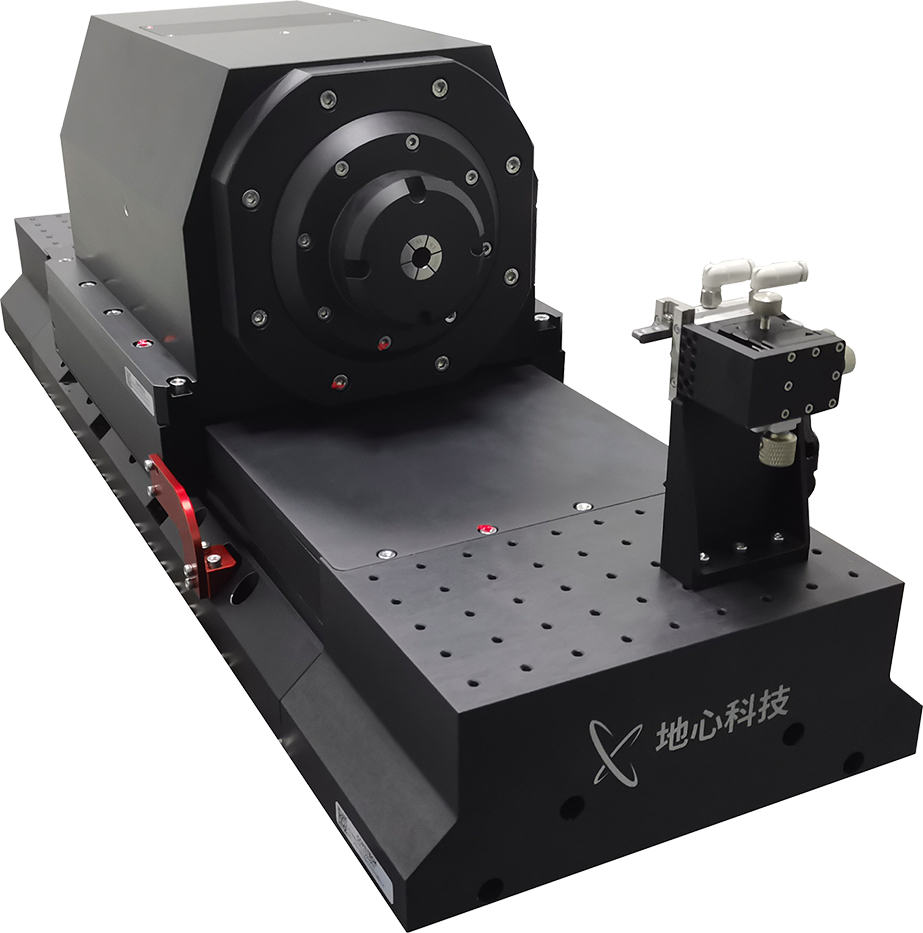
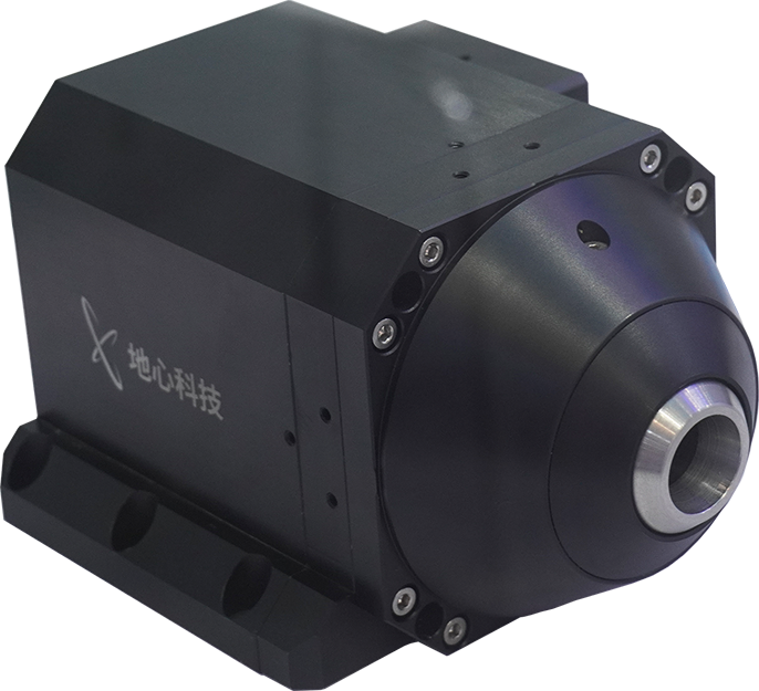
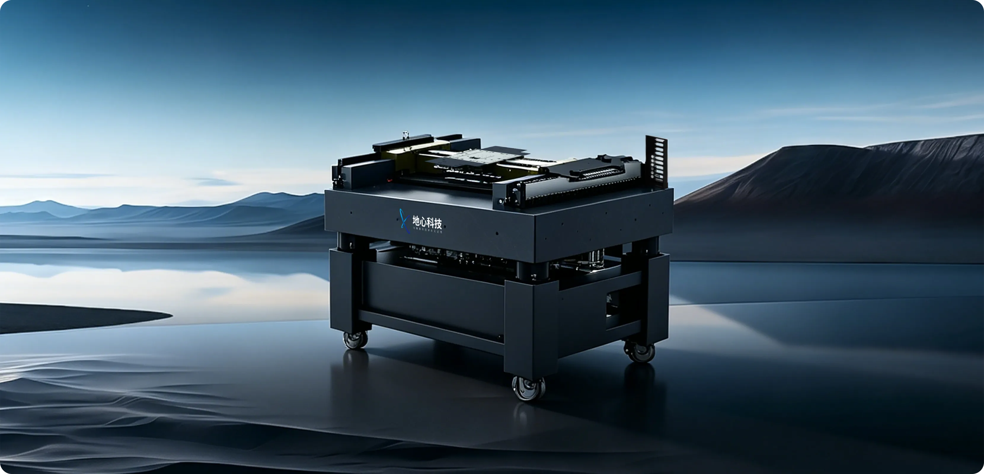
To address common challenges in fiber inspection—such as the stringent demands of high‑magnification imaging, difficulty in identifying tiny defects, low manual alignment efficiency, and difficulty in maintaining continuous focus on curved or large‑size samples—Ground Motion Technology has partnered with a leading photonic application solution provider to develop a 3‑axis motion platform specifically for fiber inspection, suitable for the vast majority of fiber inspection scenarios.In this solution, the XY axes drive precise sample movement in the horizontal plane, while the Z axis adjusts the vertical height. Combined with closed‑loop feedback algorithms, the platform achieves fast automatic alignment, significantly improving inspection efficiency and repeatability compared to manual operation.
When inspecting the sidewalls of bent fibers or testing large samples such as fiber preforms, the Z axis can be dynamically adjusted in coordination with the XY scanning position, ensuring that the imaging focus remains on the sample surface throughout the process, thus avoiding blurring caused by sample warpage or tilted placement.
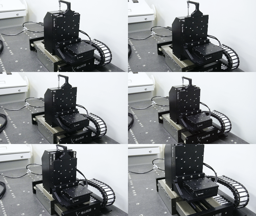
Platform Advantages:
XYZ three‑axis positioning accuracy < ±100 nm;
XY axes maximum speed 200 mm/s, Z axis maximum speed 20 mm/s;
X axis minimum step 10 nm, in‑position stability ±10 nm;
Y and Z axes minimum step 5 nm, in‑position stability ±3 nm;
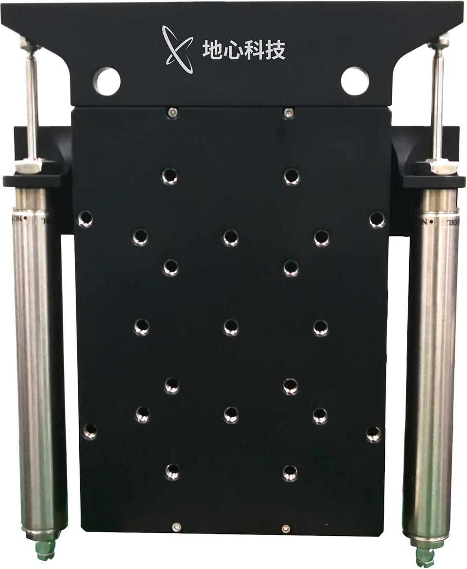
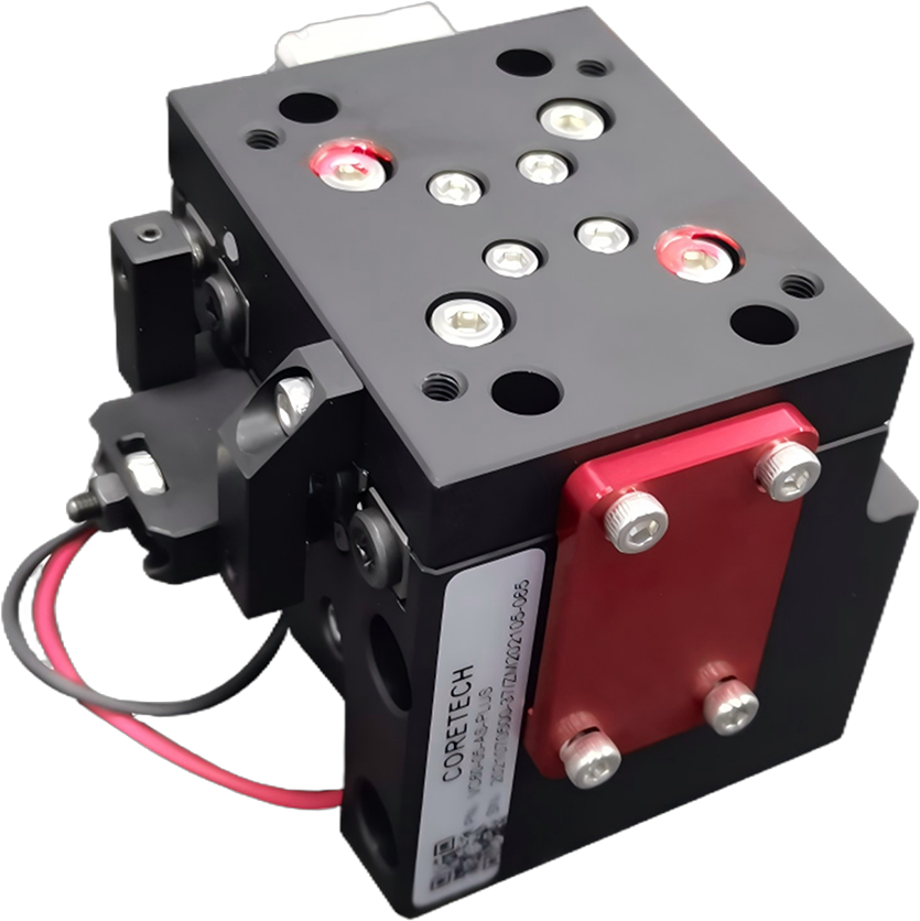
As the application requires heavy load capacity, we use a Z‑axis pneumatic cylinder as a counterweight, which effectively prevents object drop during power failure while also improving response speed.
Beyond bare‑fiber inspection, the high‑precision motion platform is also applicable to production and inspection processes for fiber preforms, FA (Fiber Array) units, and more, providing critical support across the entire value chain—from raw material preparation and device manufacturing to line operation and maintenance.
总结SUMMARY
Featured News
3D Scanning Imaging of Brain Neural Networks: High-Precision Motion Stages Enhancing Accuracy and Efficiency
2026.06.03
Breaking the Boundaries of Chip Yield Improvement: Geocentric Technology's Wafer Spiral Inspection Solution Accelerates Quality and Efficiency in the Industry
2026.06.03
Gene Sequencing: Solving Auto‑Focus and Equal‑Interval Triggering Issues to Enhance Measurement Accuracy and Efficiency
2026.06.03
 Back to List